Overview of 4x4 Keypad
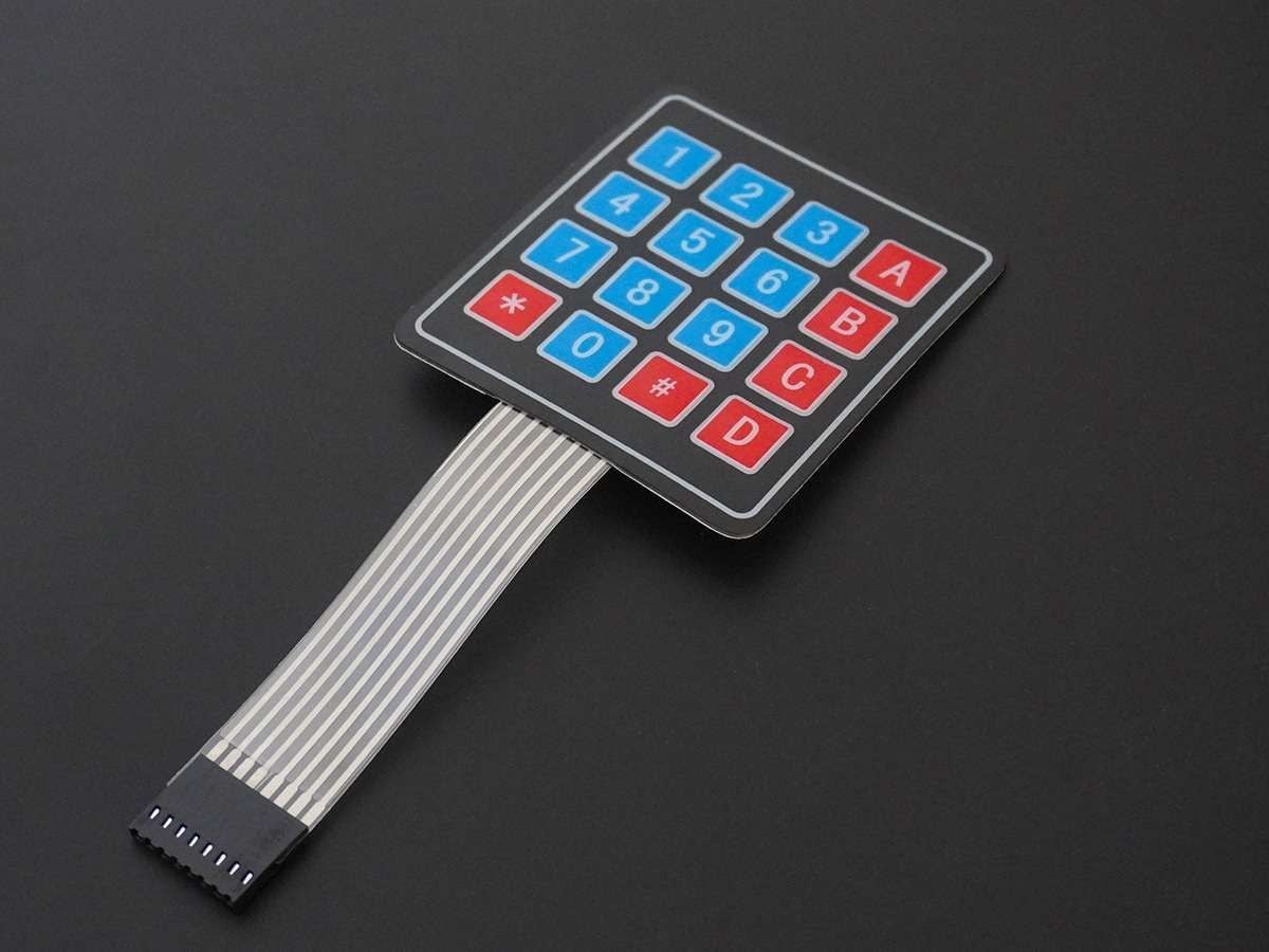
Keypad is used as an input device to read the key pressed by the user and to process it.
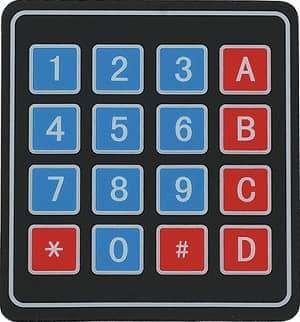
4x4 keypad consists of 4 rows and 4 columns. Switches are placed between the rows and columns.
A key press establishes a connection between the corresponding row and column, between which the switch is placed.
For more information about the keypad and how to use it, refer to the topic 4x4 Keypad in the sensors and modules section.
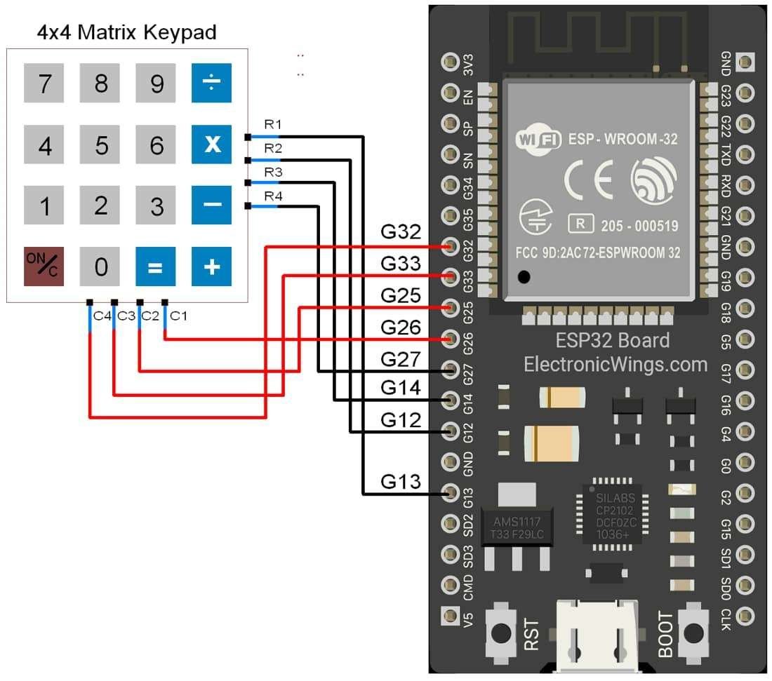
4x4 Keypad Hardware Connection ESP32
Read the 4x4 Keypad using ESP32
Reading the key pressed on 4x4 keypad and displaying it on the serial terminal of Arduino.
Here, we will be using the Keypad library by Mark Stanley and Alexander Brevig.
Download this library from here.
Extract the library and add it to the libraries folder path of Arduino IDE.
For information about how to add a custom library to the Arduino IDE and use examples from it, refer Adding Library To Arduino IDE in the Basics section.
Once the library has been added to the Arduino IDE, open the IDE and open the example sketch for CustomKeypad from the library added.
Note: If you do not connect the pins according to this function, the key press identification will not give results according to the keypad you have defined.
byte rowPins[ROWS] = {R1, R2, R3, R4}; /* connect to the row pinouts of the keypad */
byte colPins[COLS] = {C1, C2, C3, C4}; /* connect to the column pinouts of the keypad */
Code for 4x4 Keypad Serial Monitor using ESP32
/* @file CustomKeypad.pde
|| @version 1.0
|| @author Alexander Brevig
|| @contact [email protected]
||
|| @description
|| | Demonstrates changing the keypad size and key values.
|| #
*/
#include <Keypad.h>

const byte ROWS = 4; /* four rows */
const byte COLS = 4; /* four columns */
/* define the symbols on the buttons of the keypads */
char hexaKeys[ROWS][COLS] = {
  {'0','1','2','3'},
  {'4','5','6','7'},
  {'8','9','A','B'},
  {'C','D','E','F'}
};

byte rowPins[ROWS] = {13, 12, 14, 27}; /* connect to the row pinouts of the keypad */
byte colPins[COLS] = {26, 25, 33, 32}; /* connect to the column pinouts of the keypad */

/* initialize an instance of class NewKeypad */
Keypad customKeypad = Keypad( makeKeymap(hexaKeys), rowPins, colPins, ROWS, COLS);

void setup(){
Serial.begin(9600);
}

void loop(){
  char customKey = customKeypad.getKey();

  if (customKey){
Serial.println(customKey);
  }
}
- Now upload the code. (While uploading the code make sure your ESP32 board is in the boot mode.)
- After uploading the code open the serial monitor and set the baud rate to 115200 to see the output.
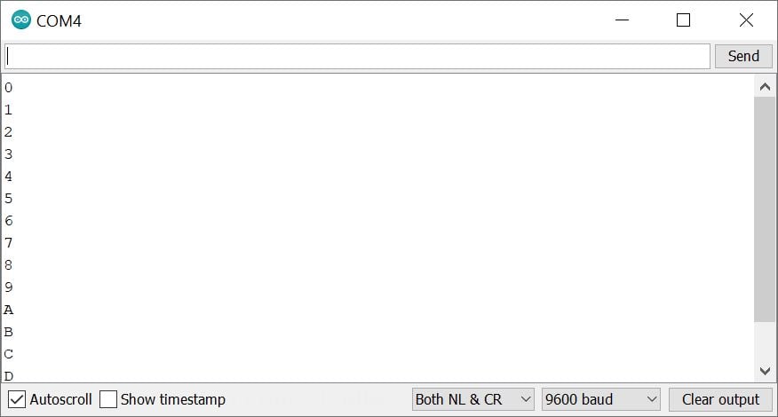
ESP32 serial monitor output for 4x4 Keypad
Let’s Understand the code
First initialize the Keypad Library.
#include <Keypad.h>Define the key matrix here we have used 4x4 keypad which means 4 rows and 4 columns
const byte ROWS = 4; /* four rows */
const byte COLS = 4; /* four columns */
Define the symbols on the buttons of the keypads in 4x4 array
char hexaKeys[ROWS][COLS] = {
  {'0','1','2','3'},
  {'4','5','6','7'},
  {'8','9','A','B'},
  {'C','D','E','F'}
};
Set the pin numbers for rows and columns of the keypad
byte rowPins[ROWS] = {13, 12, 14, 27}; /* connect to the row pinouts of the keypad */
byte colPins[COLS] = {26, 25, 33, 32}; /* connect to the column pinouts of the keypad */
Initialize an instance of class NewKeypad
Keypad customKeypad = Keypad( makeKeymap(hexaKeys), rowPins, colPins, ROWS, COLS);
In setup function
We have initiated the serial communication with a 9600 Baud rate.
void setup(){
Serial.begin(9600);
}
In loop function
Here we can detect the key using customKeypad.getKey() function and print it on the serial monitor.
void loop(){
  char customKey = customKeypad.getKey();

  if (customKey){
Serial.println(customKey);
  }
}
Components Used |
||
|---|---|---|
| 4x4 Keypad Module Keypad is an input device which is generally used in applications such as calculator, ATM machines, computer etc. |
X 1 | |
| 4x3 Matrix Keypad 4x3 Matrix Keypad |
X 1 | |
| 4x4 Matrix Keypad 4x4 Matrix Keypad |
X 1 | |
| ESP32 WROOM WiFi Development Tools - 802.11 ESP32 General Development Kit, embeds ESP32-WROOM-32E, 4MB flash. |
X 1 | |
Downloads |
||
|---|---|---|
|
|
ESP32_Keypad_v0_1 | Download |