Introduction
General-Purpose Input Output (GPIO) is a digital pin of a controller or module. It can be used as input or output for various practical applications.
If we want to read the switch’s state, sensor data, etc then we need to configure it as input. And if we want to control the LED brightness, motor rotation, show text on display, etc then we need to configure it as output.
ESP32 GPIO Pins
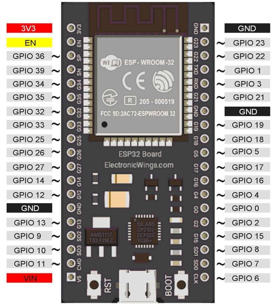
ESP32 board has various digital IO pins which can be used for input/output devices. The following image shows the digital IO pins of ESP32.
Let’s see the digital input and output of ESP32.
Digital Output
ESP32’s digital pins can be configured as an output to drive output devices. We have to configure these pins to use as output.
To configure these pins, the pinMode() function is used which set the direction of the pin as input or output.
pinMode(pin no, Mode)
This function is used to configure GPIO pin as input or output.
pin no number of pin whose mode we want to set.
Mode INPUT, OUTPUT or INPUT_PULLUP
e.g. pinMode (3, OUTPUT); //set pin 3 as outputThese ESP32’s pins can source 40mA and sink 28mA current, which is sufficient to drive led, LCD display, etc. but not sufficient for motors, relays, etc.
Caution: While connecting devices at ESP32 output pins use a resistor. If any connected device to ESP32 withdraws current more than 40 mA from the ESP32 then it will damage the ESP32 pin or module.
These pins produce output in terms of HIGH (3.3 V) or LOW (0 V). We can set output on these pins using the digitalWrite() function.
digitalWrite(pin no, Output value)
This function is used to set output as HIGH (3.3 V) or LOW (0 V)
pin no number of a pin whose mode we want to set.
Output value HIGH or LOW
e.g. digitalWrite (3, HIGH);Digital Input
To read data from a sensor or any device/circuit, we need to configure the digital pin as an input. ESP32 pins are set as digital input (default). So, there is no need to configure the pin as an input.
To configure the pin as digital input, the pinMode() function is used. We can read data from the GPIO pin using the digitalRead() function.
digitalRead(pin)
It is used to read data from a specified GPIO pin.
Digital Input with Pull-up Resistor
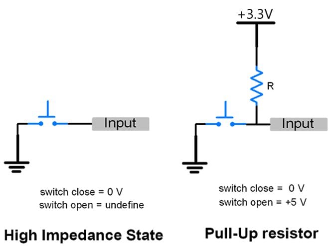
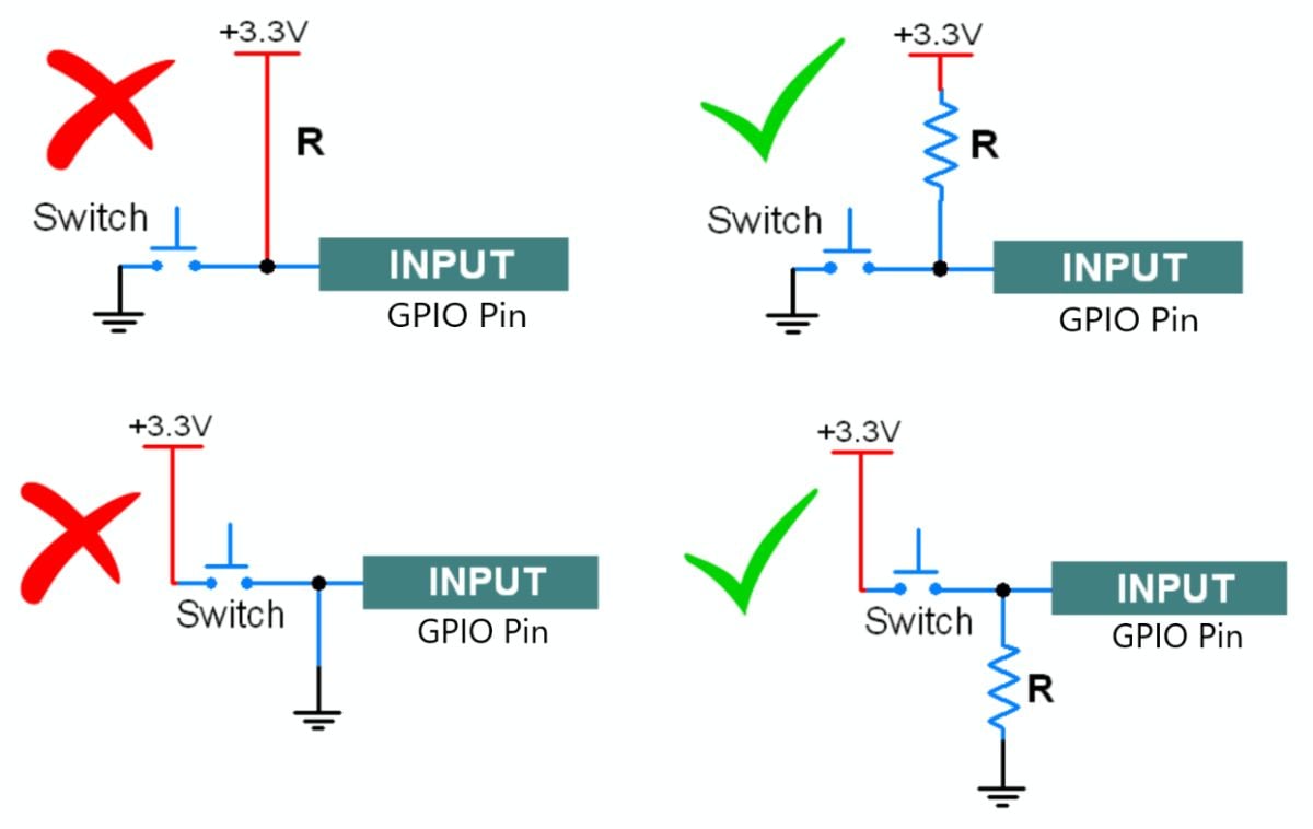
- Sometimes switching between one state to another or pins configured as input with nothing connected to them may arise a situation of a High-impedance state i.e. floating state. This state may report random changes in the pin state.
- To avoid this state, there is an option n of adding pull-a up (to +3.3V) or pull-down (to Gnd) resistor which helps to set the input to a known state. The following shows the high impedance (undefine) state and pull-up resistor.
- ESP32 has an in-built configurable pull-up resistor. These resistors enable using
pinMode()with mode set to INPUT_PULLUP. When connecting a device or sensor to a pin configured as input with pull-up, the other end should be connected to the ground.
e.g. pinMode (3, INPUT_PULLUP);- We can configure input pull-up in another way too. If we set the direction of the pin as input and then write a HIGH value on that pin will turn on the pull-up resistor. In other manner, if we write HIGH the on pin configured as OUTPUT and then configure that pin as input will also enable the pull-up resistor.
   e.g.
   pinMode (3, INPUT);        //set pin as input
   digitalWrite (3, HIGH);    //setting high on input pin enables pull-up
Caution: GPIO34-39 can only be set as input mode and does not have software-enabled pullup or pulldown functions.
| GPIO Pin | IO Type |
| GPIO34 | Input Only |
| GPIO35 | Input Only |
| GPIO36 | Input Only |
| GPIO37 | Input Only |
| GPIO38 | Input Only |
| GPIO39 | Input Only |
Blink LED Using ESP32
Let’s write a program for led blinking using ESP32.
Sketch for LED Blinking using ESP32
void setup() {
  pinMode(0, OUTPUT);         // sets the digital pin 0 as output
}

void loop() {
	digitalWrite(0, HIGH);      // sets the digital pin 0 on
	delay(1000);                // waits for a second
	digitalWrite(0, LOW);       // sets the digital pin 0 off
	delay(1000);                // waits for a second
}
Output
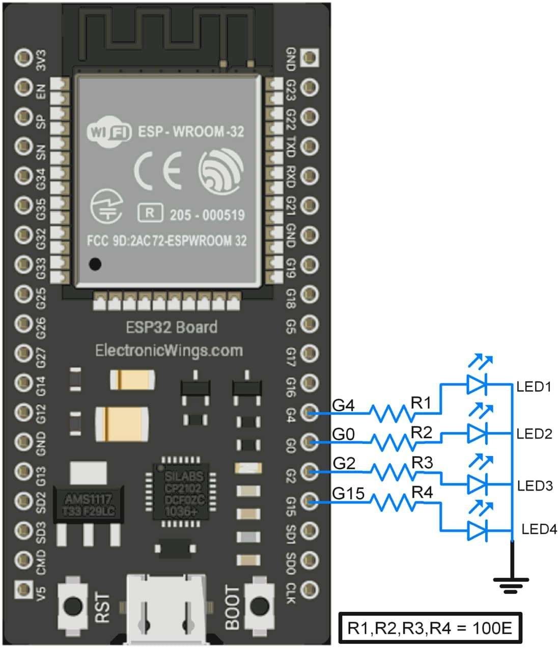
Sequentially Turning LED ON-OFF using ESP32
Let’s turn ON-OFF led sequentially. Here first, we will turn four LEDs ON one by one which means LED1 will be ON first then LED1 and LED2 will be ON, and so on. When at last all four LEDs will get ON then turn them off in reverse sequence one by one. That means turn LED4 OFF then turn LED3 OFF and so on.
Four LEDs are connected to pin D4, D0, D2, and D15 of ESP32.
Sketch for Sequential LED ON-OFF using ESP32
void setup() {
  //set gpio pin {0,4,2,15} as output
  pinMode(0, OUTPUT);
  pinMode(4, OUTPUT);
  pinMode(2, OUTPUT);
  pinMode(15, OUTPUT);
}

void loop() {
 digitalWrite(4, HIGH);       // sets the digital pin 4 on
 delay(1000);                 // waits for a second
 digitalWrite(0, HIGH);       // sets the digital pin 0 on
 delay(1000);                 // waits for a second
 digitalWrite(2, HIGH);       // sets the digital pin 2 on
 delay(1000);                 // waits for a second
 digitalWrite(15, HIGH);      // sets the digital pin 15 on
 delay(1000);                 // waits for a second

 digitalWrite(15, LOW);       // sets the digital pin 15 off
 delay(1000);                 // waits for a second
 digitalWrite(2, LOW);        // sets the digital pin 2 off
 delay(1000);                 // waits for a second
 digitalWrite(0, LOW);        // sets the digital pin 0 off
 delay(1000);                 // waits for a second
 digitalWrite(4, LOW);        // sets the digital pin 4 off
 delay(1000);                 // waits for a second
}
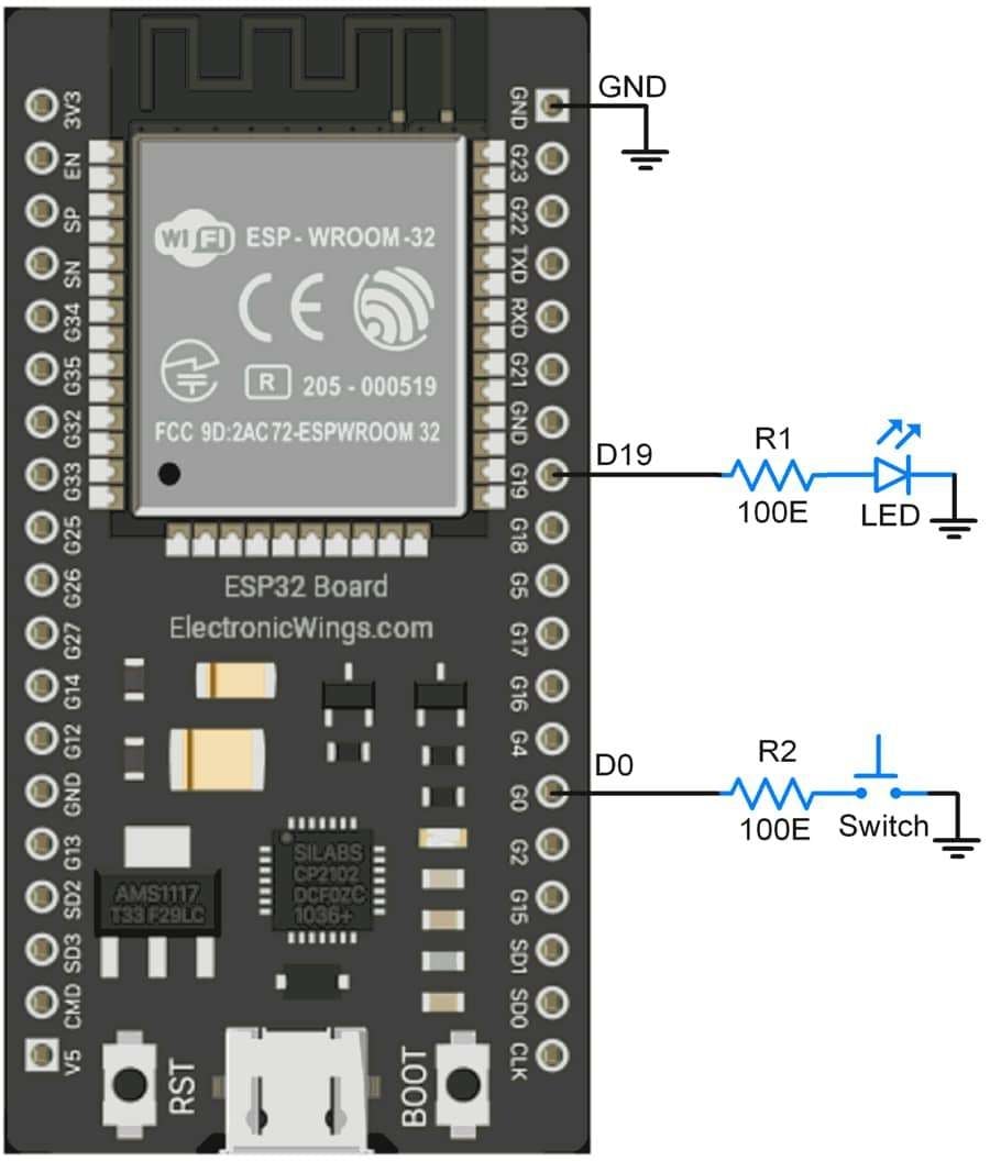
Control LED via Switch using ESP32
Let’s control LED ON-OFF using a switch interfaced to ESP32.
Interfacing Diagram
Sketch for controlling LED using switch
int pushButton = 0;
int LED = 19;

void setup() {
 	// make the pushbutton's pin an input:
 	pinMode(pushButton, INPUT_PULLUP); //configure pin as input with pullup enabled
 	pinMode(LED, OUTPUT);              //configure pin as output
}

void loop() {
	// read the input pin:
	int buttonState = digitalRead(pushButton);
	digitalWrite(LED, (!(buttonState))); 	//turn led on when switch pressed
	delay(1);        						// delay in between reads for stability
}
GPIO Cautions:
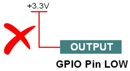
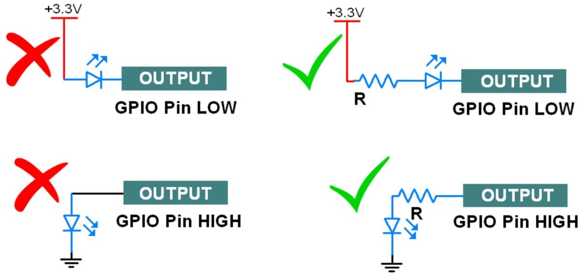
- If the GPIO pin defines as an OUTPUT LOW then don’t connect this pin to VCC, it will get short circuit and large current flow will damage your controller or GPIO pin.
- If the GPIO Pin defines as an OUTPUT HIGH then don’t connect this pin to Ground, it will draw large current which will damage your controller or GPIO pin.

- For switch connection always use a pull-up or pull-down (based on your coding logic). Always use pull UP/pull down resistor inside the microcontroller or connect an external resistor.
- Don’t connect the direct VCC pin to the GPIO pins, otherwise it will short the power supply when you press the switch.
- Kindly check following scenarios:
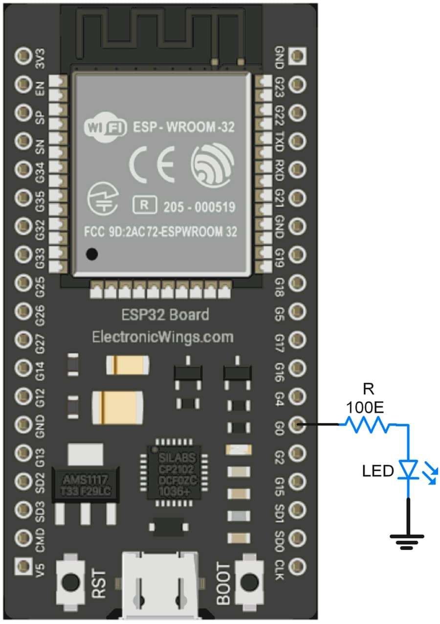
- While interfacing the led always connect a series resistor to limit the current, otherwise LED will burn.
Components Used |
||
|---|---|---|
| ESP32 WROOM WiFi Development Tools - 802.11 ESP32 General Development Kit, embeds ESP32-WROOM-32E, 4MB flash. |
X 1 | |