Overview of TCS3200 Color Sensor
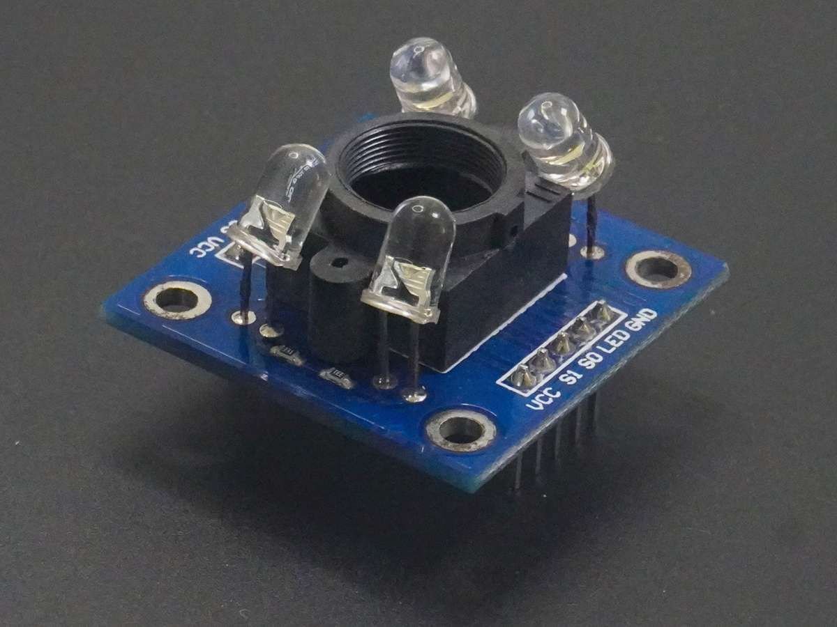
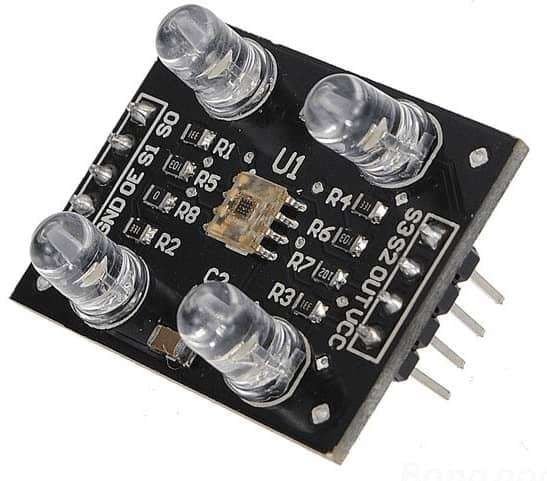
- Color Sensor Module has 4 LEDs with TCS3200 Color Sensor IC.
- Module is designed in such way a that 4 bright LEDs will light the object and reflections from that object will strike the TCS3200 Color Sensor IC to detect the color of an object.
- As its name gives us a clear idea about its application, it is basically used to detect the color of an object. It has a variety of applications in industrial, medical as well as consumer’s areas.
Note that, as per TCS3200 datasheet, the TCS3200 product is not designed to use in critical applications, where failure or malfunction of this product may result in any lives injury or death. Any such use by a customer is completely at the customer’s risk.
Let’s see about TCS3200 Color Sensor IC
- TCS3200 is a programmable color to frequency converter, which consists of configurable photodiode and current to frequency converter.
- TCS3200 gives square wave output with frequency directly proportional to the light sensitivity.
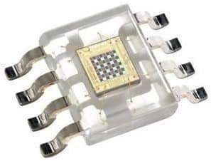
- It consists of an 8x8 array of photodiodes i.e. 64 photodiodes.
- From total of 64 photodiodes, 16 photodiodes have Red filters, 16 photodiodes have Green filters, 16 photodiodes have Blue filters, and 16 photodiodes are Clear with No filters.
- All photodiodes of the same color are connected in parallel.
- This sensor gives us object color in form of RGB (Red, Green, Blue) values, from which we can define the object color.
TCS3200 Module Pinout and Description
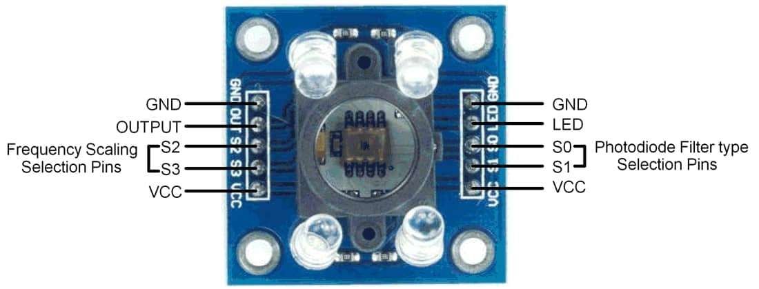
Pin 7:8 – S0:S1: Output frequency scaling selection pins
These two pins are used to scale the frequency of current to frequency converter.
Table. Frequency Scaling Selection pins
| S0 | S1 | Output Frequency Scaling (f0) | Min o/p Frequency | Typ o/p Frequency |
|---|---|---|---|---|
| 0 | 0 | Power Down Mode | - | - |
| 0 | 1 | Output frequency is 2% of current to frequency converter’s output. | 10 KHz | 12 KHz |
| 1 | 0 | Output frequency is 20% of current to frequency converter’s output. | 100 K | 120 K |
| 1 | 1 | Output frequency is 100% of current to frequency converter’s output. | 500 K | 600 K |
Pin 9 – LED (Active Low): Output Enable
Pin 1&10 – GND
GND= Power Supply Ground.
Pin 5&6 – VCC
VCC= Supply Voltage to the sensor.
Pin 2 – Output
This pin gives output in the form of a train of pulses. The duty cycle of these pulses is fixed to 50% and the frequency of these pulses is varying according to the input light.
Pin 3:4 – S2:S3 – Photodiode filter type selection pins
Table. Photodiode type selection
| S2 | S3 | Photodiode Type with their respective Filter |
|---|---|---|
| 0 | 0 | Red |
| 0 | 1 | Blue |
| 1 | 0 | Clear |
| 1 | 1 | Green |
These color filters are used to pass the respective color while other colors gets blocked. For example, when choose the red filter, only red incident light can get through, blue and green will be prevented. So, we can get the red-light intensity.
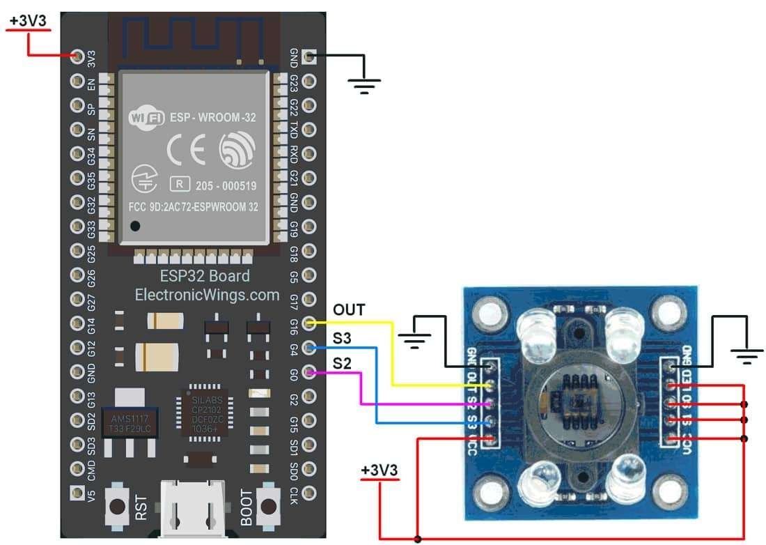
TCS3200 Color Sensor Hardware Connection with ESP32
Calibrate TCS3200 Color Sensor using ESP32
Measuring the RGB color value and display on a web server and serial monitor of Arduino.
Here, the output of TCS3200 is given to the ESP32 as shown in the figure below.
How to Calibrate the TCS3200?
- Upload the below TCS3200 Calibration Code on your ESP32.
- Set the TCS3200 Sensor on the white surface and get the minimum RGB Values.
- After that set the sensor on the black surface and get the maximum RGB values.
Code for TCS3200 Calibration using ESP32
#define S2 0 /*Define S2 Pin Number of ESP32*/
#define S3 4 /*Define S3 Pin Number of ESP32*/
#define sensorOut 16 /*Define Sensor Output Pin Number of ESP32*/
/*Define int variables*/
int Red = 0;
int Green = 0;
int Blue = 0;
int Frequency = 0;
void setup() {
pinMode(S2, OUTPUT); /*Define S2 Pin as a OUTPUT*/
pinMode(S3, OUTPUT); /*Define S3 Pin as a OUTPUT*/
pinMode(sensorOut, INPUT); /*Define Sensor Output Pin as a INPUT*/
Serial.begin(115200); /*Set the baudrate to 115200*/
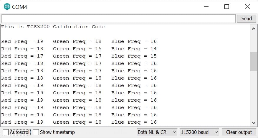
Serial.print("This is TCS3200 Calibration Code");
}
void loop() {
Red = getRed();
delay(200); /*wait a 200mS*/
Green = getGreen();
delay(200); /*wait a 200mS*/
Blue = getBlue();
delay(200); /*wait a 200mS*/
Serial.print("Red Freq = ");
Serial.print(Red); /*Print Red Color Value on Serial Monitor*/
Serial.print(" ");
Serial.print("Green Freq = ");
Serial.print(Green); /*Print Green Color Value on Serial Monitor*/
Serial.print(" ");
Serial.print("Blue Freq = ");
Serial.println(Blue); /*Print Blue Color Value on Serial Monitor*/
}
int getRed() {
digitalWrite(S2,LOW);
digitalWrite(S3,LOW);
Frequency = pulseIn(sensorOut, LOW); /*Get the Red Color Frequency*/
return Frequency;
}
int getGreen() {
digitalWrite(S2,HIGH);
digitalWrite(S3,HIGH);
Frequency = pulseIn(sensorOut, LOW); /*Get the Green Color Frequency*/
return Frequency;
}
int getBlue() {
digitalWrite(S2,LOW);
digitalWrite(S3,HIGH);
Frequency = pulseIn(sensorOut, LOW); /*Get the Blue Color Frequency*/
return Frequency;
}
- Now upload the code. (While uploading the code make sure your ESP32 board is in the boot mode.)
- After uploading the code open the serial monitor and set the baud rate to 115200 then reset the ESP32 board.
Output of Calibration Code on Serial Monitor
Code for Reading TCS3200 RGB over Serial Monitor using ESP32
/*
  ESP32 TCS3200 Color sensor
  http:://www.electronicwings.com
*/

#define S2 0          /*Define S2 Pin Number of ESP32*/
#define S3 4          /*Define S3 Pin Number of ESP32*/
#define sensorOut 16  /*Define Sensor Output Pin Number of ESP32*/

/*Enter the Minimum and Maximum Values which getting from Calibration Code*/
int R_Min = 5;  /*Red minimum value*/
int R_Max = 38; /*Red maximum value*/
int G_Min = 4;  /*Green minimum value*/
int G_Max = 42; /*Green maximum value*/
int B_Min = 4;  /*Blue minimum value*/
int B_Max = 35; /*Blue maximum value*/

/*Define int variables*/
int Red = 0;
int Green = 0;
int Blue = 0;

int redValue;
int greenValue;
int blueValue;
int Frequency;

void setup() {
  pinMode(S2, OUTPUT);        /*Define S2 Pin as a OUTPUT*/
  pinMode(S3, OUTPUT);        /*Define S3 Pin as a OUTPUT*/
  pinMode(sensorOut, INPUT);  /*Define Sensor Output Pin as a INPUT*/
  Serial.begin(115200);       /*Set the baudrate to 115200*/
  delay(1000);                /*Wait for 1000mS*/
}

void loop() {
  Red = getRed();
  redValue = map(Red, R_Min,R_Max,255,0); /*Map the Red Color Value*/
  delay(200);

  Green = getGreen();
  greenValue = map(Green, G_Min,G_Max,255,0); /*Map the Green Color Value*/
  delay(200);

  Blue = getBlue();
  blueValue = map(Blue, B_Min,B_Max,255,0);   /*Map the Blue Color Value*/
  delay(200);

  Serial.print("Red = ");
  Serial.print(redValue);   /*Print Red Color Value on Serial Monitor*/
  Serial.print("    ");
  Serial.print("Green = ");
  Serial.print(greenValue); /*Print Green Color Value on Serial Monitor*/
  Serial.print("    ");
  Serial.print("Blue = ");
  Serial.println(blueValue);/*Print Blue Color Value on Serial Monitor*/
  delay(1000);              /*wait a second*/
}

int getRed() {
  digitalWrite(S2,LOW);
  digitalWrite(S3,LOW);
  Frequency = pulseIn(sensorOut, LOW); /*Get the Red Color Frequency*/
  return Frequency;
}

int getGreen() {
  digitalWrite(S2,HIGH);
  digitalWrite(S3,HIGH);
  Frequency = pulseIn(sensorOut, LOW); /*Get the Green Color Frequency*/
  return Frequency;
}

int getBlue() {
  digitalWrite(S2,LOW);
  digitalWrite(S3,HIGH);
  Frequency = pulseIn(sensorOut, LOW); /*Get the Blue Color Frequency*/
  return Frequency;
}
- Now upload the code. (While uploading the code make sure your ESP32 board is in the boot mode.)
- After uploading the code open the serial monitor and set the baud rate to 115200 then reset the ESP32 board
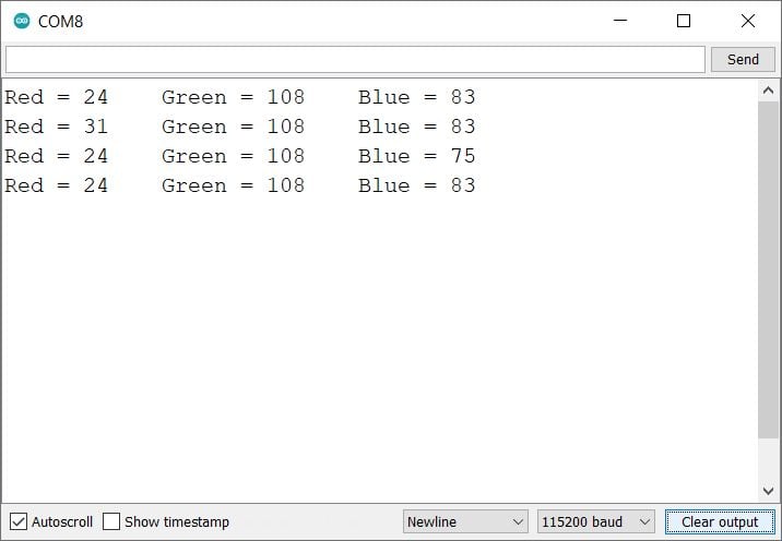
TCS3200 RGB Color Sensor Output
Let’s Understand the code
Set the pin numbers for the TCS3200 color sensor
#define S2 0          /*Define S2 Pin Number of ESP32*/
#define S3 4          /*Define S3 Pin Number of ESP32*/
#define sensorOut 16  /*Define Sensor Output Pin Number of ESP32*/
Enter the Minimum and Maximum RGB values which getting from Calibration Code
int R_Min = 5;  /*Red minimum value*/
int R_Max = 38; /*Red maximum value*/
int G_Min = 4;  /*Green minimum value*/
int G_Max = 42; /*Green maximum value*/
int B_Min = 4;  /*Blue minimum value*/
int B_Max = 35; /*Blue maximum value*/
Then define the variables for the RGB values.
int Red = 0;
int Green = 0;
int Blue = 0;

int redValue;
int greenValue;
int blueValue;
int Frequency;
In setup function
Set the sensor pin as an INPUT mode We have initiated the serial communication with a 115200 Baud rate.
void setup() {
  pinMode(S2, OUTPUT);        /*Define S2 Pin as a OUTPUT*/
  pinMode(S3, OUTPUT);        /*Define S3 Pin as a OUTPUT*/
  pinMode(sensorOut, INPUT);  /*Define Sensor Output Pin as a INPUT*/
  Serial.begin(115200);       /*Set the baudrate to 115200*/
  delay(1000);                /*Wait for 1000mS*/
}
In loop function
In the loop function, we are getting the RGB values and print on the serial monitor.
Get the red, green, and blue color values and map them into 0 to 255 and store them in assigned variables.
Here we have used the Arduino map() function to convert these values into RGB values, using our calibration values as a reference.
Red = getRed();
redValue = map(Red, R_Min,R_Max,255,0); /*Map the Red Color Value*/
delay(200);

Green = getGreen();
greenValue = map(Green, G_Min,G_Max,255,0); /*Map the Green Color Value*/
delay(200);

Blue = getBlue();
blueValue = map(Blue, B_Min,B_Max,255,0);   /*Map the Blue Color Value*/
delay(200);
Print RGB values on the serial monitor.
Serial.print("Red = ");
Serial.print(redValue);   /*Print Red Color Value on Serial Monitor*/
Serial.print("    ");
Serial.print("Green = ");
Serial.print(greenValue); /*Print Green Color Value on Serial Monitor*/
Serial.print("    ");
Serial.print("Blue = ");
Serial.println(blueValue);/*Print Blue Color Value on Serial Monitor*/
delay(1000);              /*wait a second*/
Other function
In the loop section, we call three functions getRed(), getGreen() and getBlue() to obtain the pulse width. Let’s examine getRed() as an example.
The getRed() function gives the red pulses. It starts by setting the photodiode red filter type selection using S2 and S3 pins. This is the only step where this function differs from its green and blue counterparts.
int getRed() {
  digitalWrite(S2,LOW);
  digitalWrite(S3,LOW);
  Frequency = pulseIn(sensorOut, LOW); /*Get the Red Color Frequency*/
  return Frequency;
}

int getGreen() {
  digitalWrite(S2,HIGH);
  digitalWrite(S3,HIGH);
  Frequency = pulseIn(sensorOut, LOW); /*Get the Green Color Frequency*/
  return Frequency;
}

int getBlue() {
  digitalWrite(S2,LOW);
  digitalWrite(S3,HIGH);
  Frequency = pulseIn(sensorOut, LOW); /*Get the Blue Color Frequency*/
  return Frequency;
}
Sketch for Reading TCS3200 RGB over ESP32 Web Server
Now let’s take another example to display the same readings of the TCS3200 on the web server using the Arduino IDE.
Before uploading the code make sure you have added your SSID and Password as follows.
const char* ssid = "*Your SSID*";         /*Enter Your SSID*/
const char* password = "*Your Password*"; /*Enter Your Password*/
Sketch for Reading TCS3200 RGB over Web Server using ESP32
#include <WiFi.h>
#include <WebServer.h>
#include "html.h"

WebServer server(80);

const char* ssid = "***Your SSID***";         /*Enter Your SSID*/
const char* password = "***Your Password***"; /*Enter Your Password*/

#define S2 0          /*Define S2 Pin Number of ESP32*/
#define S3 4          /*Define S3 Pin Number of ESP32*/
#define sensorOut 16  /*Define Sensor Output Pin Number of ESP32*/

/*Enter the Minimum and Maximum Values which getting from Calibration Code*/
int R_Min = 0;  /*Red minimum value*/
int R_Max = 0;  /*Red maximum value*/
int G_Min = 0;  /*Green minimum value*/
int G_Max = 0;  /*Green maximum value*/
int B_Min = 0;  /*Blue minimum value*/
int B_Max = 0;  /*Blue maximum value*/

/*Define int variables*/
int Red = 0;
int Green = 0;
int Blue = 0;

int redValue;
int greenValue;
int blueValue;
int Frequency;

void MainPage() {
  String _html_page = html_page;              /*Read The HTML Page*/
  server.send(200, "text/html", _html_page);  /*Send the code to the web server*/
}

void Colors() {
  String data = "[\""+String(redValue)+"\",\""+String(greenValue)+"\",\""+String(blueValue)+"\"]";
  server.send(200, "text/plane", data);
}

void setup() {
  pinMode(S2, OUTPUT);        /*Define S2 Pin as a OUTPUT*/
  pinMode(S3, OUTPUT);        /*Define S3 Pin as a OUTPUT*/
  pinMode(sensorOut, INPUT);  /*Define Sensor Output Pin as a INPUT*/
  Serial.begin(115200);       /*Set the baudrate to 115200*/

  pinMode(sensorOut, INPUT);  /*Define sensorOut as a input Pin*/

  WiFi.mode(WIFI_STA);        /*Set the WiFi in STA Mode*/
  WiFi.begin(ssid, password);
  Serial.print("Connecting to ");
  Serial.println(ssid);
  delay(1000);                /*Wait for 1000mS*/
  while(WiFi.status() != WL_CONNECTED)
  {
    Serial.print(".");
    delay(200);
  } /*Wait while connecting to WiFi*/
  Serial.print("Connected to ");
  Serial.println(ssid);
  Serial.print("Your Local IP address is: ");
  Serial.println(WiFi.localIP());       /*Print the Local IP*/

  server.on("/", MainPage);             /*Display the Web/HTML Page*/
  server.on("/readColors", Colors);     /*Display the updated Distance value(CM and INCH)*/
  server.begin();                       /*Start Server*/
  delay(1000);                          /*Wait for 1000mS*/
}

void loop() {
  Red = getRed();
  redValue = map(Red, R_Min,R_Max,255,0); /*Map the Red Color Value*/
  delay(200);

  Green = getGreen();
  greenValue = map(Green, G_Min,G_Max,255,0); /*Map the Green Color Value*/
  delay(200);

  Blue = getBlue();
  blueValue = map(Blue, B_Min,B_Max,255,0);   /*Map the Blue Color Value*/
  delay(200);

  Serial.print("Red = ");
  Serial.print(redValue);   /*Print Red Color Value on Serial Monitor*/
  Serial.print("    ");
  Serial.print("Green = ");
  Serial.print(greenValue); /*Print Green Color Value on Serial Monitor*/
  Serial.print("    ");
  Serial.print("Blue = ");
  Serial.println(blueValue);/*Print Blue Color Value on Serial Monitor*/
  server.handleClient();
  delay(1000);              /*wait a second*/
}

int getRed() {
  digitalWrite(S2,LOW);
  digitalWrite(S3,LOW);
  Frequency = pulseIn(sensorOut, LOW); /*Get the Red Color Frequency*/
  return Frequency;
}

int getGreen() {
  digitalWrite(S2,HIGH);
  digitalWrite(S3,HIGH);
  Frequency = pulseIn(sensorOut, LOW); /*Get the Green Color Frequency*/
  return Frequency;
}

int getBlue() {
  digitalWrite(S2,LOW);
  digitalWrite(S3,HIGH);
  Frequency = pulseIn(sensorOut, LOW); /*Get the Blue Color Frequency*/
  return Frequency;
}
- Now upload the code. (While uploading the code make sure your ESP32 board is in the boot mode.)
- After uploading the code open the serial monitor and set the baud rate to 115200 then reset the ESP32 board and check the IP address as shown in the below image
.png)
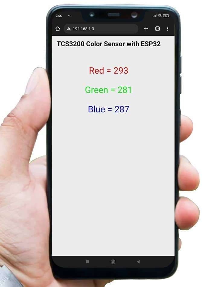
Output on the webserver
- Now open any mobile browser and type the IP address which is shown in the serial monitor and hit the enter button.
- If all are ok, then the web page will start the showing current RGB values on the web server like in the below image.
Note: make sure your ESP32 and mobile are connected to the same router/ Wi-fi Device, if they are connected to the same Wi-Fi source then only you will be able to view the web page. If there is no Wi-Fi router, or Wi-fi Source, you can create Wi-Fi Hotspot via smartphone and connect it to ESP32.
Let’s Understand the code
To understand this code, please refer to the basics guide of “How to create the ESP32 Server”.
Once you get the basics of ESP32 server creation, it will be very simple to understand the code.
This code starts with important header files and libraries, In WiFi.h file contains all ESP32 WiFi related definitions, here we have used them for network connection purposes.
The WebServer.h file supports handling the HTTP GET and POST requests as well as setting up a server. In the html.h file contains all the web page code.
#include <WiFi.h>
#include <WebServer.h>
#include "html.h"
Let’s define HTTP port i.e., Port 80 as follows
WebServer server(80);
Setup Function
In the setup function, first we set the WiFi as an STA mode and connect to the given SSID and password.
WiFi.mode(WIFI_STA);          /*Set the WiFi in STA Mode*/
WiFi.begin(ssid, password);
Serial.print("Connecting to ");
Serial.println(ssid);
delay(1000);                  /*Wait for 1000mS*/
while(WiFi.waitForConnectResult() != WL_CONNECTED){Serial.print(".");}
After successfully connecting to the server print the local IP address on the serial window.
Serial.print("Your Local IP address is: ");
Serial.println(WiFi.localIP());     /*Print the Local IP*/
Handling Client Requests and Serving the Page
To handle the client request, we use server.on() function.
It takes two parameters, The first is the requested URL path, and the second is the function name, which we want to execute.
As per the below code, when a client requests the root (/) path, the “MainPage()” function executes.
Also, when a client requests the “/readColors” path, The Colors() function will be called.
server.on("/", MainPage);           /*Client request handling: calls the function to serve HTML page */
server.on("/readColors", Colors);     /*Display the updated Distance value(CM and INCH)*/
Now start the server using server.begin() function.
server.begin(); /*Start Server*/
Functions for Serving HTML
We have defined the complete HTML page in a file named “html.h” and added it to the header file. With the following function, we are sending the complete page to the client via server.send() function.
While sending, we are passing the first parameter “200” which is the status response code as OK (Standard response for successful HTTP requests).
Second parameter is the content type as “text/html“, and the third parameter is html page code.
void MainPage() {
  String _html_page = html_page;              /*Read The HTML Page*/
  server.send(200, "text/html", _html_page);  /*Send HTM page to Client*/
}
Now in the below function only we are sending the updated RGB values to the web page.
void Colors() {
  String data = "[\""+String(redValue)+"\",\""+String(greenValue)+"\",\""+String(blueValue)+"\"]";
  server.send(200, "text/plane", data);
}
Loop Function
Now to handle the incoming client requests and serve the relevant HTML page, we can use handleClient() function. It executing relevant server.on() as a callback function although it is defined in void setup()
So, it continuously serves the
server.handleClient();
HTML Web Page Code
/*
  ESP32 HTML WebServer Page Code
  http:://www.electronicwings.com
*/

const char html_page[] PROGMEM = R"RawString(
<!DOCTYPE html>
<html>
  <style>
    body {font-family: sans-serif;}
    h1 {text-align: center; font-size: 30px;}
    p.a {text-align: center; color: #FF0000; font-size: 40px;}
    p.b {text-align: center; color: #00FF00; font-size: 40px;}
    p.c {text-align: center; color: #0000FF; font-size: 40px;}
  </style>

<body>
  <h1>TCS3200 Color Sensor with ESP32 </h1><br>
  <p class="a">Red = <span id="_R">0</span></p>
  <p class="b">Green = <span id="_G">0</span></p>
  <p class="c">Blue = <span id="_B">0</span></p>

<script>
  setInterval(function() {
    var xhttp = new XMLHttpRequest();
    xhttp.onreadystatechange = function() {
      if (this.readyState == 4 && this.status == 200) {
        const text = this.responseText;
        const myArr = JSON.parse(text);
       document.getElementById("_R").innerHTML = myArr[0];
       document.getElementById("_G").innerHTML = myArr[1];
       document.getElementById("_B").innerHTML = myArr[2];

      }
    };
    xhttp.open("GET", "readColors", true);
    xhttp.send();
  },100);
</script>
</body>
</html>
)RawString";
Let’s understand the code step by step
All html pages start with the <!DOCTYPE html> declaration, it is just information to the browser about what type of document is expected.
<!DOCTYPE html>The html tag is the container of the complete html page which represents on the top of the html code.
<html>Now here we are defining the style information for a web page using the <style> tag. Inside the style tag we have defined the font name, size, color, and test alignment.
  <style>
    body {font-family: sans-serif;}
    h1 {text-align: center; font-size: 30px;}
    p {text-align: center; color: #4CAF50; font-size: 40px;}
  </style>
Inside the body, we are defining the document body, in below we have used headings, and paragraphs if you want you can add images, hyperlinks, tables, lists, etc. also.
On the web page, we are displaying the heading of the page, and inside a paragraph RBG readings.
Now RGB value updates under the span id which is manipulated with JavaScript using the id attribute.
<body>
  <h1>TCS3200 Color Sensor with ESP32 </h1><br>
  <p class="a">Red = <span id="_R">0</span></p>
  <p class="b">Green = <span id="_G">0</span></p>
  <p class="c">Blue = <span id="_B">0</span></p>
Now, this is the javascript that comes under the <script> tag, this is also called a client-side script.
<script>
In setInterval() method we are calling the function at every 50mS intervals.
setInterval(function() {},50);Here we are creating the html XMLHttpRequest object
var xhttp = new XMLHttpRequest();The xhttp.onreadystatechange event is triggered every time the readyState changes and the readyState holds the status of the XMLHttpRequest.
Now in the below code, the ready state is 4 means the request finished and response is ready and the status is 200 which means OK.
xhttp.onreadystatechange = function() {
if (this.readyState == 4 && this.status == 200) {
const myArr = JSON.parse(this.responseText);
Now here is the main thing, we are updating the RGB values in html page using _R, _G, and _B id.
document.getElementById("_R").innerHTML = myArr[0];
document.getElementById("_G").innerHTML = myArr[1];
document.getElementById("_B").innerHTML = myArr[2];
Here we used the AJAX method to send the updated values to the server without refreshing the page.
In the below function we have used the GET method and sent the readColors function which we defined in the main code asynchronously.
xhttp.open("GET", "readColors", true);Send the request to the server using xhttp.send(); function.
xhttp.send();
Close the script
</script>Close the body
</body>Close the html.
</html>
Components Used |
||
|---|---|---|
| TCS3200 Colour Sensor Module Color Sensor Module (TCS3200) can detect colors. It is generally used for color identification by their RGB values. |
X 1 | |
| ESP32 WROOM WiFi Development Tools - 802.11 ESP32 General Development Kit, embeds ESP32-WROOM-32E, 4MB flash. |
X 1 | |