Description
.jpg)
- MAX7219 is a popular integrated circuit that can be used to drive an 8x8 LED matrix display.
- The MAX7219 IC contains a 16-bit shift register, an 8-bit latch, and a constant-current LED driver for each of the eight rows in the display.
- Each row in the LED matrix is connected to a constant-current LED driver, which provides consistent brightness across all of the LEDs in that row.
- The MAX7219 can control up to eight rows, so a standard 8x8 LED matrix display can be connected directly to the IC.
- The MAX7219 can be controlled using a three-wire interface, which consists of a data input pin, a clock input pin, and a chip select pin.
- By sending specific commands to the IC, the user can set the brightness of the display, turn individual LEDs on or off, and even scroll text across the display.
- In addition to controlling a single LED matrix display, the MAX7219 can also be used to control multiple displays in a cascaded configuration.
- By connecting the data output pin of one MAX7219 IC to the data input pin of another IC, multiple displays can be controlled with a single microcontroller.
MAX7219 Display Module Specification:
- Integrated Circuit: MAX7219
- LED Matrix Display: 8x8
- Maximum Rows: 8
- Constant-Current LED Drivers: 1 per row
- Interface: SPI Interface
- Cascadable: Yes, up to 8 devices
- Maximum Brightness: 16 levels
- Display Scrolling: Yes
- Operating Voltage: 4.0V - 5.5V
- Operating Current: 330 mA (maximum wheel all digits on)
- Operating Temperature: -40°C to +85°C
MAX7219 Display Pin Diagram:
.jpg)
MAX7219 Display Pin Description:
- VCC: Positive power supply voltage input (4.0V - 5.5V)
- GND: Ground reference
- DIN: Data input for the three-wire interface
- CS: Chip select input for the three-wire interface
- CLK: Clock input for the three-wire interface
MAX7219 LED Display Interfacing with ESP32
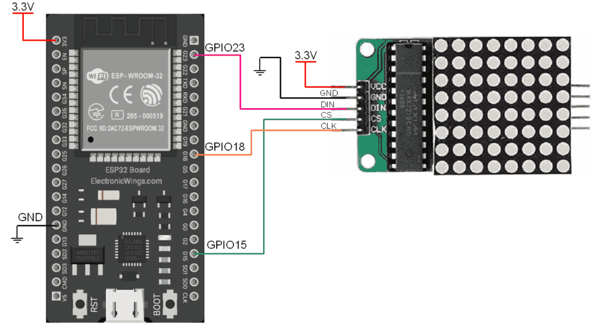
Hardware Connection Details
| ESP32 Pins | MAX7219 Display Module Pins |
| GPIO23 (MOSI) | DIN |
| GPIO18 (Clk) | Clk |
| GPIO15 (CS) | CS |
| 3.3V | VCC |
| GND | GND |
MAX7219 LED Display Code for ESP32 using Arduino IDE
#include <LedControl.h>

int DIN = 23;
int CS =  15;
int CLK = 18;

LedControl lc=LedControl(DIN,CLK,CS,0);

byte smile[8]=   {0x3C,0x42,0xA5,0x81,0xA5,0x99,0x42,0x3C};
byte neutral[8]= {0x3C,0x42,0xA5,0x81,0xBD,0x81,0x42,0x3C};
byte frown[8]=   {0x3C,0x42,0xA5,0x81,0x99,0xA5,0x42,0x3C};

void setup(){
  lc.shutdown(0,false);       //The MAX72XX is in power-saving mode on startup
  lc.setIntensity(0,15);      // Set the brightness to maximum value
  lc.clearDisplay(0);         // and clear the display
}

void loop(){
  printByte(smile);
  delay(1000);
  printByte(neutral);
  delay(1000);
  printByte(frown);
  delay(1000);
  lc.clearDisplay(0);
  delay(100);
}

void printByte(byte character []){
  int i = 0;
  for(i=0;i<9;i++)
  {
    lc.setRow(0,i,character[i]);
  }
}
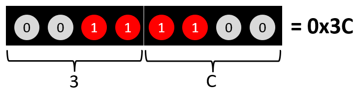
Know how to calculate the array value for any type of text or image
.PNG)
Array = 0x3C, 0x42, 0XA5, 0x81, 0x81, 0xA5, 0x99, 0x42, 0x3C
Let’s Understand the code
First, the LedControl library is included to simplify the communication between the microcontroller and the MAX7219 IC.
#include <LedControl.h>Next, three integer variables are declared to represent the digital input (DIN), chip select (CS), and clock (CLK) pins of the MAX7219 IC.
These pins are connected to the corresponding pins of the ESP32 Board.
int DIN = 23;
int CS =  15;
int CLK = 18;
A LedControl object named "lc" is created using the LedControl library and the DIN, CS, and CLK pin variables.
LedControl lc=LedControl(DIN,CLK,CS,0);Then, three arrays of bytes are defined that represent three different facial expressions: a smile, neutral, and frown.
Each array contains 8 bytes that represent the LED matrix display patterns for each row of the display.
byte smile[8]=   {0x3C,0x42,0xA5,0x81,0xA5,0x99,0x42,0x3C};
byte neutral[8]= {0x3C,0x42,0xA5,0x81,0xBD,0x81,0x42,0x3C};
byte frown[8]=   {0x3C,0x42,0xA5,0x81,0x99,0xA5,0x42,0x3C};
In setup function
In the setup function, the MAX7219 IC is initialized.
The shutdown function is called to exit power-saving mode, the intensity function is called to set the brightness to maximum, and the clearDisplay function is called to clear the display.
lc.shutdown(0,false);       //The MAX72XX is in power-saving mode on startup
lc.setIntensity(0,15);      // Set the brightness to maximum value
lc.clearDisplay(0);         // and clear the display
In loop function
In the loop function, the printByte function is called three times with the smile, neutral, and frown arrays.
The printByte function sets each row of the LED matrix display to the corresponding byte in the character array, effectively displaying the desired facial expression.
The display is then cleared for a short period of time before the loop repeats.
printByte(smile);
delay(1000);
printByte(neutral);
delay(1000);
printByte(frown);
delay(1000);
lc.clearDisplay(0);
delay(100);
The printByte function takes an input byte array representing one row of the LED matrix display.
It iterates through each byte in the array and calls the setRow function of the lc object to set the corresponding row of the LED matrix display to the byte value.
void printByte(byte character []){
  int i = 0;
  for(i=0;i<9;i++)
  {
    lc.setRow(0,i,character[i]);
  }
}
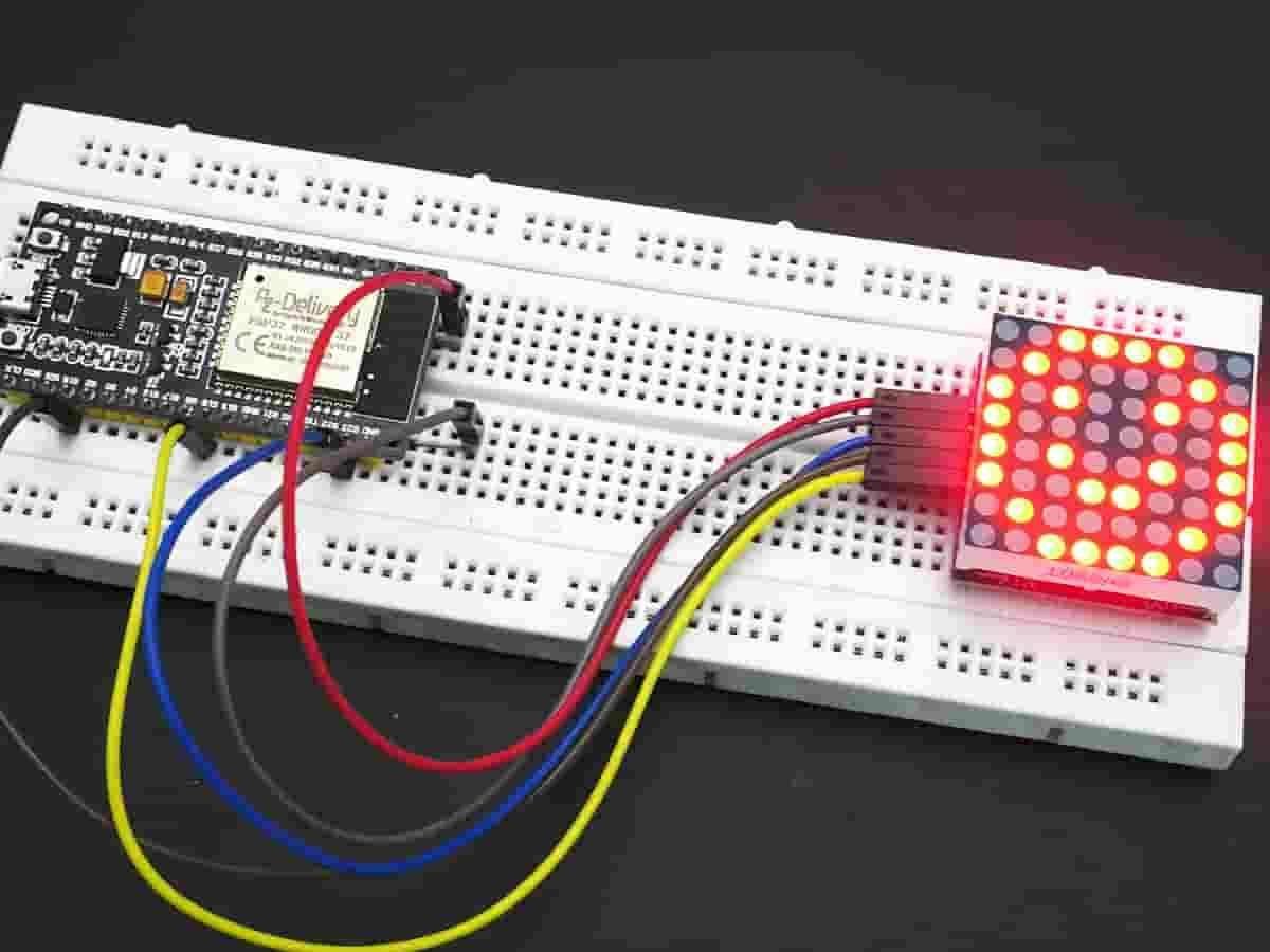
Output
Downloads |
||
|---|---|---|
|
|
MAX7219_ESP32_Code | Download |