Introduction
What is DAC (Digital to Analog Converter)?
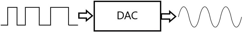
- A Digital to Analog Converter is a device that converts digital values (0 and 1) to a set of continuous analog voltages.
- There are two types of methods which are converting digital signals to analog signals one is a binary weighted method and another is the R/2R ladder method.
- DACs are mostly used in DSPs (Digital Signal Processing), music players, mobile phones, televisions, power supplies, etc.
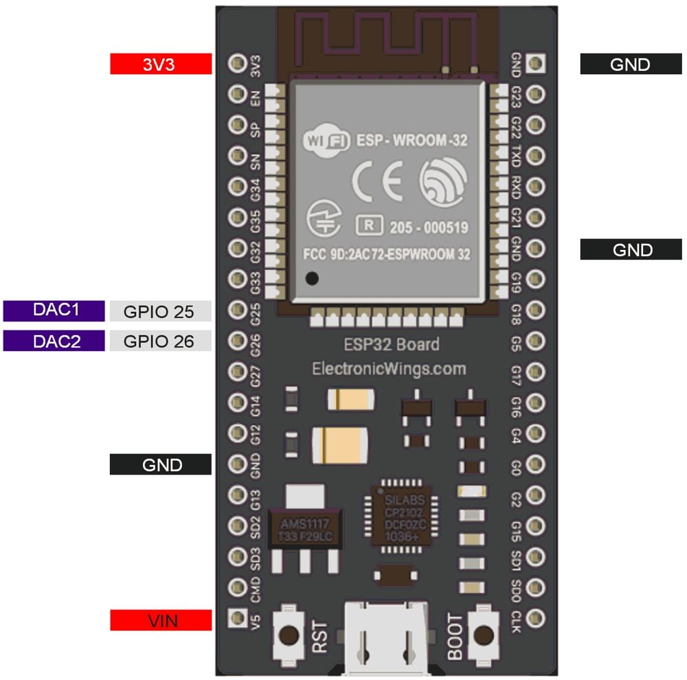
ESP32 has two 8-bit DAC (digital to analog converter) channels internally which are connected to GPIO25 (Channel 1) and GPIO26 (Channel 2).
8-bit DAC means, ESP32 can convert the digital input (0 to 255) to equivalent analog output.
With 3.3Volt, our ESP32 will provide the 0-volt for digital 0 and 3.3volt for digital 255. However, in practical, output by DAC is a bit lower i.e. max 3.25v for 255.
DAC Pins of ESP32
Important DAC Functions for ESP32
dacWrite(pin, value)
This function is used to set the DAC value for a given pin or DAC channel.
pin: Set the DAC pin number
value: Set the value in the range of 0 - 255 (equals 0V - 3.3V).
dacDisable(pin)
This function is used to disable DAC output on a given pin or DAC channel.
pin: Set the DAC pin number
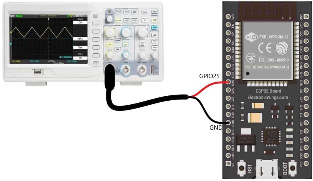
DSO Connection Diagram with ESP32
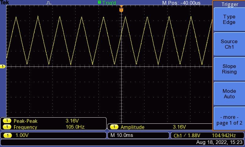
Generate Triangular Wave using ESP32
Let’s write a code for ESP32 to generate the triangular wave using DAC.
Sketch for DAC Triangular Wave Generation using ESP32
#define DAC1 25       //Define Pin no 25 for DAC Output

void setup(){}

void loop() {
/*
* here we are using 8 bit DAC so 2^8=255
* Means 0 = 0V and 255=3.3V
*/
 for (int i=0; i<255; i++){
   dacWrite(DAC1, i);          //write on DAC Pin
 }

 for (int i=255; i>=0; i--){
   dacWrite(DAC1, i);          //write on DAC Pin
 }
}
Output
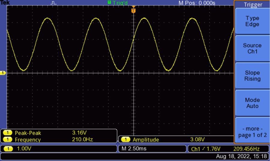
Generate Sine Wave using ESP32
Now let’s do something interesting, let’s generate the sine wave at the output of the DAC. For that use the same interfacing diagram as above.
Sketch for DAC Sine Wave Generation using ESP32
Here we need to calculate the sinewave values and store it in the array of 256 values.
/*
 ESP32 DAC Sine Wave Generation
 http:://www.electronicwings.com
*/

int Sin_Array[256];                 // Define array to store sine wave values
float Period = (2*PI)/256;          // Define the sine wave conversion factor
float Rad_Angle;

void setup(){
 for(int Angle=0; Angle<256; Angle++) {
   Rad_Angle = Angle*Period;       // calculate the angle in radian
   Sin_Array[Angle] = (sin(Rad_Angle)*127)+128;  // caclulate the anagle and shift by 128
 }
}

void loop(){
 for(int i=0;i<256;i++)
   dacWrite(25,Sin_Array[i]);       // Write the sinewave vale on the DCA pin
}
Output
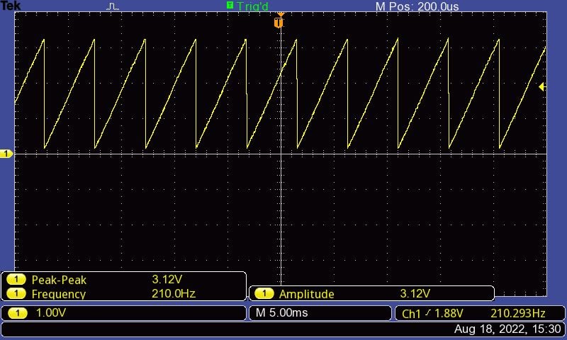
Generate Sawtooth Wave using ESP32
Now in this last example let’s write a code to generate the sawtooth wave using DAC.
Sketch for DAC Sawtooth Wave Generation using ESP32
/*
  ESP32 DAC Sawtooth Wave Generation
  http:://www.electronicwings.com
*/


#define DAC1 25       //Define Pin no 25 for DAC Output

void setup(){}

void loop() {
/*
* here we are using 8-bit DAC so 2^8=255
* Means 0 = 0V and 255=3.3V
*/
  for (int i=0; i<255; i++){
    dacWrite(DAC1, i);          //write on DAC Pin
  }

}
Output
Components Used |
||
|---|---|---|
| ESP32 WROOM WiFi Development Tools - 802.11 ESP32 General Development Kit, embeds ESP32-WROOM-32E, 4MB flash. |
X 1 | |