Introduction
- When we interface sensors to the microcontroller, the output of the sensor many times is analog. To analyze and understand it, we need to convert it into a digital signal.
- Hence, ADC (Analog to Digital converter) is used. It converts an analog signal into digital So it can be processed by the microcontroller.
- There are many applications where ADC is used like biometric applications, Sensor monitoring, Gas leakage detection, etc.
ESP32 ADC
ESP32 Wroom module has 16 onboard ADC channels which can be used to read analog signals in the range 0-3.3V.
It has a 12-bit ADC means it will give digital values in the range of 0 – 4096 (2^12). This is called resolution which indicates the number of discrete values it can produce over the range of analog values.
Digital Output Value Calculation
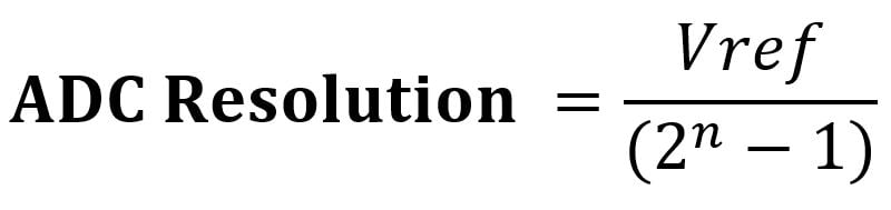
With Vref=3.3V ADC resolution of The ESP32 is: 805.66 uV
.png)
Were,
Vref - The reference voltage is the maximum voltage limit that the ADC can convert.
To keep things simple, let us consider that Vref is 3.3V,
For 0 Vin, digital o/p value = 0
For 3.3 Vin, digital o/p value = 4096 (12-bit)
For 2.5 Vin, digital o/p value = 3103 (12-bit)
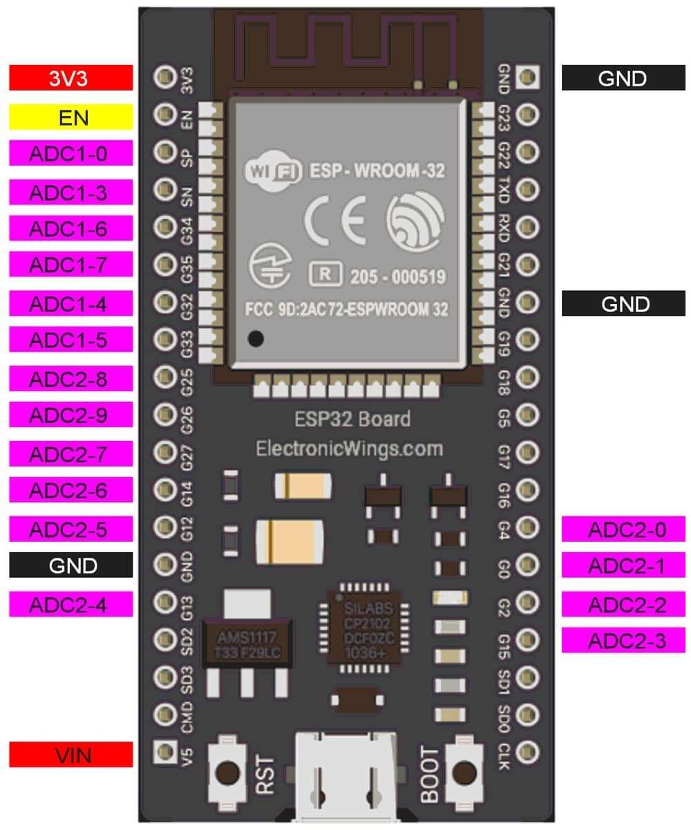
ADC Pins of ESP32
Functions for ESP32 ADC
analogRead (pin)
This function is used to read analog values from a specified analog pin.
pin - number of the analog pin which we want to read
returns - digital value 0 – 4095
e.g. analogRead(A0) //read analog value at A0 channel
analogReference (type)
This function is used for configuring the reference voltage used for analog input.
Read Analog value using ESP32
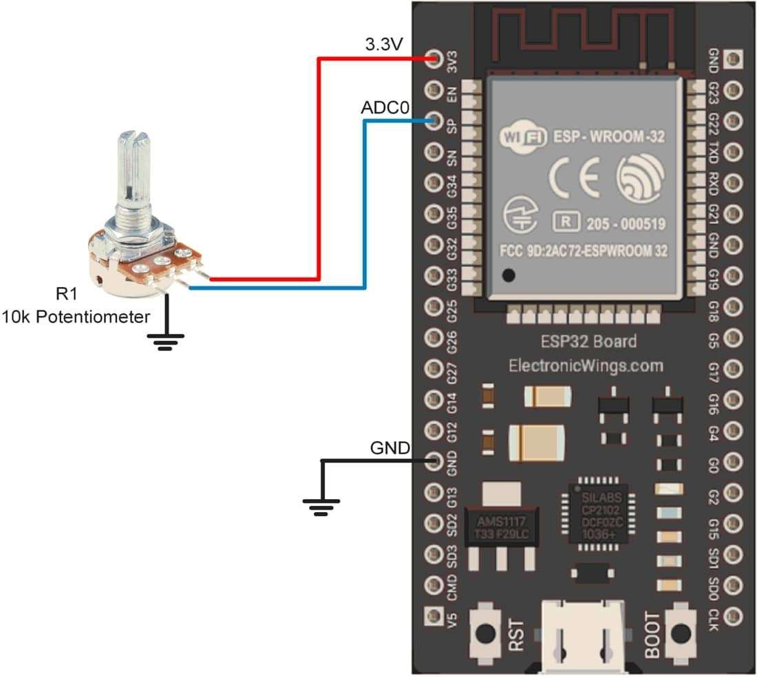
Let’s write a program to read varying analog values generated using a potentiometer that is connected to the A0 analog channel. Display the digital value on the Serial monitor which we got from the ESP32 ADC.
Interfacing Diagram
Sketch for reading an analog value
int sensorPin = A0; // input pin for the potentiometer
int digitalValue = 0;// variable to store the value coming from the sensor

void setup(){
 Serial.begin(9600);
}

void loop(){
 digitalValue = analogRead(sensorPin);// read the value from the analog channel
 Serial.print("digital value = ");
 Serial.println(digitalValue);       //print digital value on serial monitor
  delay(1000);
}
ADC Output on Serial Monitor
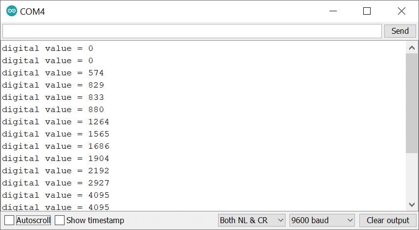
Note: If nothing is connected to the analog input channel then the analogRead() function returns the noisy fluctuating value.
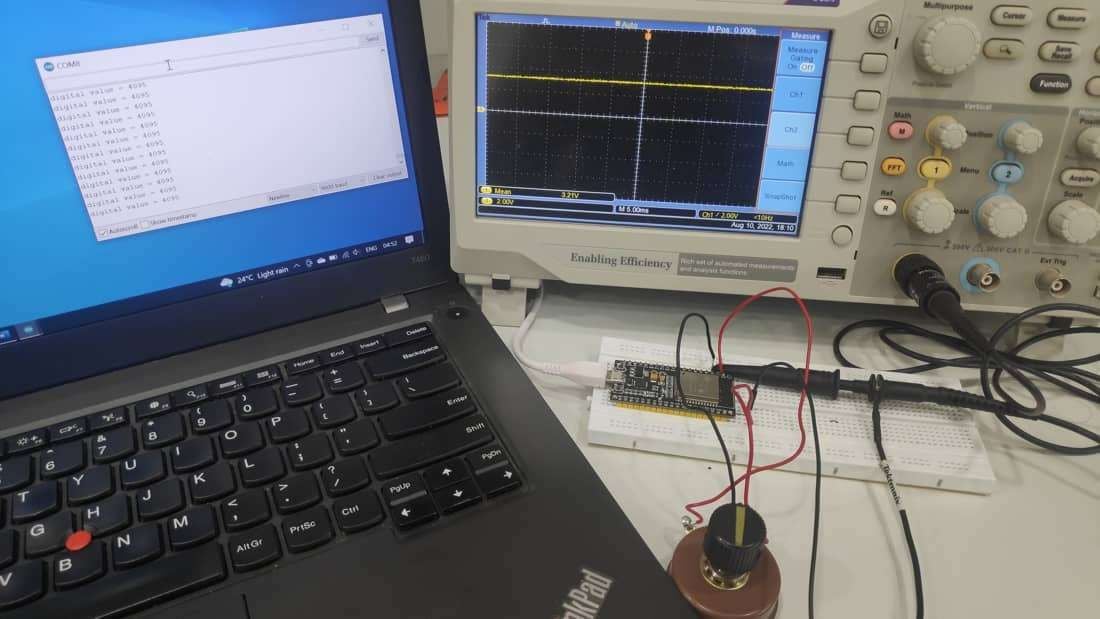
ESP32 ADC Observation
As we know the ADC gives the linear response proportional to the input. But in the ESP32 we have observed it gives a non-linear response. Let’s check our lab report in short.
Here we have connected the setup as per the above interfacing diagram the extra tool is we have connected DSO to measure the voltage. Now when we decrease the voltage from 3.3 to 0 linearly when it comes to 3.21 Volt still ESP32 shows 4095 Reding at the serial monitor after 3.32 Volt is starts decreasing the ADC count. Shown in below diagram.
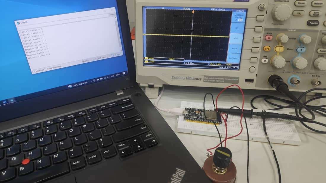
Same when we increase the voltage from 0 to 3.3 volt it shows 0 reading still voltage at 0.138 Volt. The response is shown in below diagram.
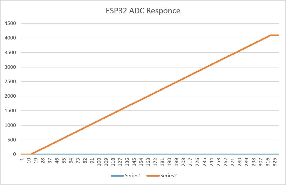
The responsive curve is shown in below chart.
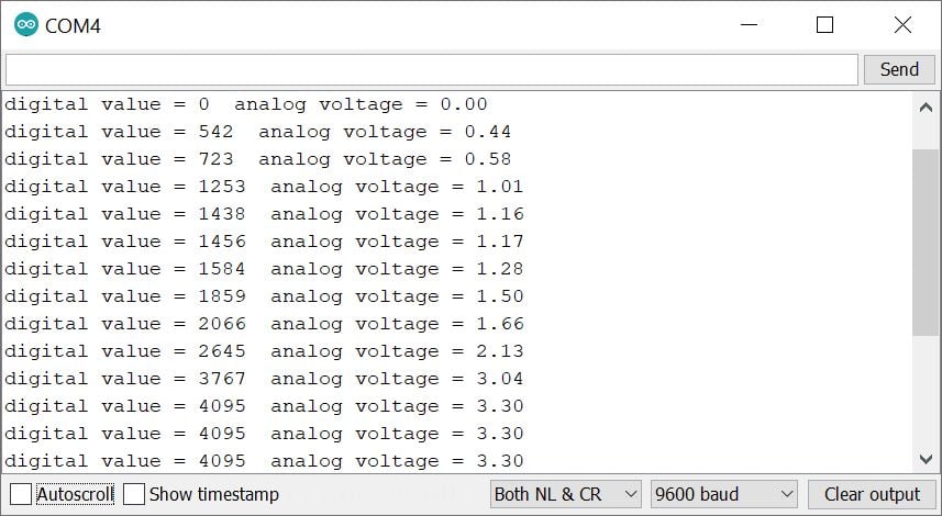
Read Analog Voltage using ESP32
As ADC provides a digital output that is proportional to an analog value. To know what is input analog value, we need to convert this digital value back to analog value through the program. To convert this digital value to the analog input voltage,
.png)
e.g., digital value = 512 and ADC is 12-bit with 3.3V Vref. But we want to know for what analog voltage it is giving the respective digital value. Then,
.png)
= 0.412V
Sketch for reading Analog Voltage using ESP32
int sensorPin = A0;  // select the input pin for the potentiometer
int digitalValue = 0;  // variable to store the value coming from the sensor
float analogVoltage = 0.00;

void setup(){
 Serial.begin(9600);
}

void loop(){
 digitalValue = analogRead(sensorPin);// read the value from the analog channel
 Serial.print("digital value = ");
 Serial.print(digitalValue);       //print digital value on serial monitor
  //convert digital value to analog voltage
 analogVoltage = (digitalValue * 3.3)/4095.00;
 Serial.print("  analog voltage = ");
  Serial.println(analogVoltage);
  delay(1000);
}
Output on Serial Window
Extra Functions supported by ESP32 ADC
ESP32 also support following extra functions in Arduino IDE.
Functions to set the ESP32 ADC resolution
analogReadResolution(bits)
This function set the size in bits to return the analogRead value, for ESP32 default resolution is 12-bit which returns the values between 0 to 4095.
bits: it determines the bits in resolution to return by ADC, you can set the resolution in between 1 to 32 bits.
Note: ESP32’s ADC resolution is 12-bit, if you set the value higher than 12-bit it sets the highest resolution (i.e. 12-bit).
Example: Set the ADC Resolution to 10-Bit only
analogReadResolution(10);
Another similar function to set the resolution is
analogSetWidth(width)
Set the size in width to return the analogRead value, for ESP32 default resolution is 12-bit which returns the values between 0 to 4095.
width: it determines the bits in resolution to return by ADC, you can set the resolution between 1 to 32 bits.
Note: ESP32’s ADC resolution is 12-bit, if you set the value higher than 12-bit it gives back to its higher resolution (i.e. 12-bit).
e.g. analogSetWidth(10);
Few other Useful functions
analogSetClockDiv(divider)
Set the clock divider for ADC, the default divider is 1.
Divider:Set the clock divider in the range of 1 to 255.
e.g. analogSetClockDiv(1);
analogSetAttenuation(attenuation)
Set the input attenuation for ALL ADC inputs, the default attenuation is ADC_11db.
attenuation: Set the attenuation ranges ADC_0db, ADC_2_5db, ADC_6db, ADC_11db
e.g. analogSetAttenuation(ADC_11db);
The following functions are also available, however at the time of testing they didn’t work.
analogSetCycles(cycles)
Set the number of clock cycles per sample, The default cycle is 0 to provide an optimal result.
Cycles: Set the cycles in the range of 1 to 255.
e.g. analogSetCycles(8);
analogSetSamples(samples)
Set number of samples in the range, default is 1, it has an effect on sensitivity has been multiplied
set the number of samples in the range. Default is 1 sample. It has an effect of increasing sensitivity.
Samples:
e.g. analogSetSamples(samples);Note: The above two functions are not works for ESP32
Components Used |
||
|---|---|---|
| ESP32 WROOM WiFi Development Tools - 802.11 ESP32 General Development Kit, embeds ESP32-WROOM-32E, 4MB flash. |
X 1 | |
Downloads |
||
|---|---|---|
|
|
ESP32_ADC_Code | Download |