Why Hardware Timers
Hardware timers are a very important feature in microcontrollers.
H/W timers are absolutely important for mission-critical applications, and precise time intervals actions.
H/W timers with ISR provide the perfect/ accurate time interval. Because of ISR, the execution is not blocked by any random behavior in program. This is very important for mission-critical tasks.
Random behavior of connecting to Wi-Fi / Internet, etc might delay mission-critical tasks. Software delay(), millis() gets impacted by other ISR and they are not precise. Using them for mission-critical task is bad idea.
So, for accuracy in time interval, mission critical tasks, etc H/W timers are very much important.
ESP32 Timers
- The ESP32 has two timer groups.
- Each one with two general-purpose hardware timers, means there are 4 total timers in the ESP32
- All the timers are based on 64-bit counters and 16-bit prescalers (Dividers).
- Prescalers are used for dividing the base clock frequency (usually 80 MHz).
- The divided frequency is provided to the timer counter for increment or decrement.
- Prescalers is 16bit, so we divide 80MHz base clock frequency from 2 to 65536, which gives us a lot of flexibility.
- Timers can be configured for counting UP or DOWN.
Alarm Generation (Timer Interrupt in ESP32)
- Timer can trigger an alarm when the timer value matches with a set value.
- This will auto-reload the timer to zero and it can trigger the interrupt (if enabled).
Programming for ESP32 Timer Interrupt (Alarm Generation)
Step1: initialize timerBegin() Function.
timer= timerBegin(0, 80, true);- This function returns a pointer to a structure of type hw_timer_t, which we will define as the timer global variable.
- We pass three values to this function, the first one is the timer to use. ESP32 has 4 hardware timers. We can put 0 to 3 values to use any which we need.
- The second value is “prescaler”, i.e. divider value to the clock frequency i.e. 80MHz. We have a 16bit prescaler so we can set any value from 2 to 65536. Here we used ‘80’, so the value after dividing will be 80MHz/80= 1MHz. This means in one second the timer will count from 0 to 1000000. With this, for each count, the timer will take 1uS (microsecond). This will make out calculation simple.
- Flag indicates the counter shall count UP(true) or Count DOWN(false).
Step2: Attach Interrupt
timerAttachInterrupt(timer, &onTimer, true);- With this we will attach the interrupt to the ISR function. So on the interrupt the function
onTimer()will execute. - First, we have to provide the pointer of the timer defined in a global variable.
- Second is the address of the function which is going to be called upon interrupt.
Step3: Define the match timer value
timerAlarmWrite(timer, 1000000, true);- “
timerAlarmWrite” function is used for defining the value for which the timer will generate the interrupt. - For 1 second delay we have defined 1000000 value. We can define any value as per our delay requirement. (500 ms= 500000, 10ms=10000, 0.8s=800000).
- For example, here we have defined the 1000000 value for 1 second delay, so timer will count from 0 to 999999 and on 1000000 it will match. This will generate the Interrupt, timer will get auto reloaded to ‘0’, and interrupt ISR function will start executing.
- However, we need to enable the interrupt/Alarm with
timerAlarmEnable(timer);function first.
Important Notes:
- The variable which will be used/ manipulated in the interrupt ISR functions should be declared with volatile Keyword. This will notify compiler and it will be stored in the RAM for faster access.
- ISR function are special kind of function, executes on interrupt. It should be short as possible. An ISR cannot have any parameters, and they shouldn’t return anything.
“Inside the attached function, delay() won’t work and the value returned by millis() will not increment. Serial data received while in the function may be lost. You should declare as volatile any variables that you modify within the attached function.”
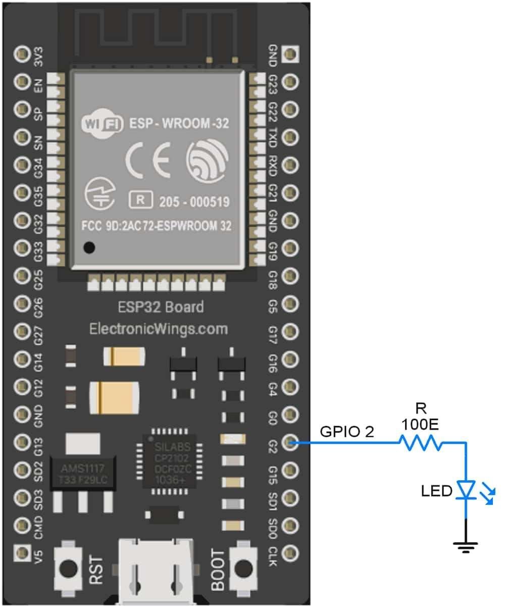
Interfacing Diagram
Code
ESP32 has only one inbuilt LED which shows the only status. Not connected to any GPIO pin
/*
Timer Interrupt in ESP32, Alarm generation in ESP32
www.electronicwings.com
*/
#define LED_PIN 2 // In some ESP32 board have inbuilt LED
volatile int interruptCounter; //for counting interrupt
int totalInterruptCounter; //total interrupt counting
int LED_STATE=LOW;
hw_timer_t * timer = NULL; //H/W timer defining (Pointer to the Structure)
portMUX_TYPE timerMux = portMUX_INITIALIZER_UNLOCKED;
void IRAM_ATTR onTimer() { //Defining Inerrupt function with IRAM_ATTR for faster access
portENTER_CRITICAL_ISR(&timerMux);
interruptCounter++;
portEXIT_CRITICAL_ISR(&timerMux);
}
void setup() {
Serial.begin(115200);
pinMode (LED_PIN, OUTPUT);
timer = timerBegin(0, 80, true); // timer 0, prescalar: 80, UP counting
timerAttachInterrupt(timer, &onTimer, true); // Attach interrupt
timerAlarmWrite(timer, 1000000, true); // Match value= 1000000 for 1 sec. delay.
timerAlarmEnable(timer); // Enable Timer with interrupt (Alarm Enable)
}
void loop() {
if (interruptCounter > 0) {
portENTER_CRITICAL(&timerMux);
interruptCounter--;
portEXIT_CRITICAL(&timerMux);
totalInterruptCounter++; //counting total interrupt
LED_STATE= !LED_STATE; //toggle logic
digitalWrite(LED_PIN, LED_STATE); //Toggle LED
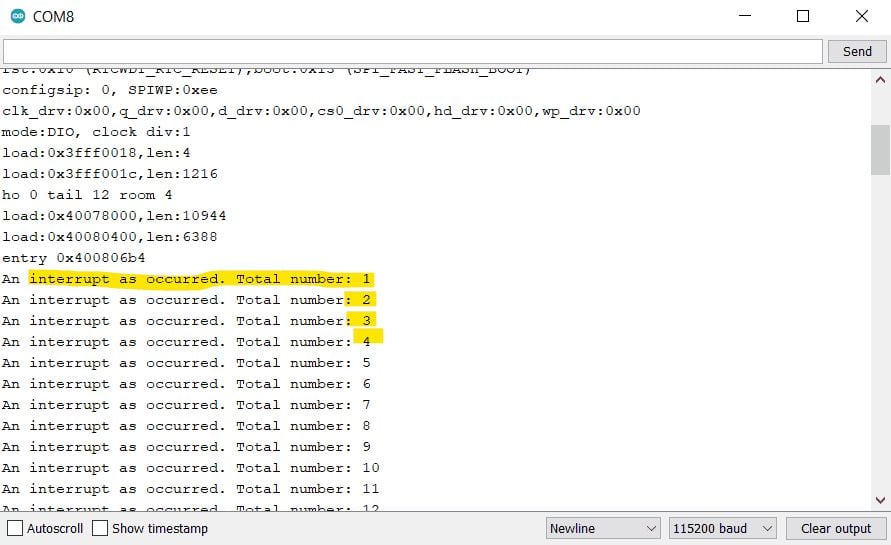
Serial.print("An interrupt as occurred. Total number: ");
Serial.println(totalInterruptCounter);
}
}
Main Function:
In Main Function, we check for the interruptCounter variable is greater than zero and if it is, we go for interrupt handing, where we decrement the variable (means acknowledging the interrupt).
Since this variable is shared with the ISR, we will do it inside a critical section, which we specify by using a portENTER_CRITICAL and a portEXIT_CRITICAL macro. Both of these calls receive as an argument the address of our global portMUX_TYPE variable.
portENTER_CRITICAL(&timerMux);
   interruptCounter--;
portEXIT_CRITICAL(&timerMux);
After then, we have toggled the LED on Board (GPIO2) and printed the output.
The ISR Function Code
We have to define the interrupt function in IRAM_ATTR attribute, so the compiler will place the code inside the RAM for faster execution. Also before updating the variable inside the ISR function, we have to specify it in the critical section.
Output
Downloads |
||
|---|---|---|
|
|
ESP32_Timer_Interrupts | Download |