Description
.jpg)
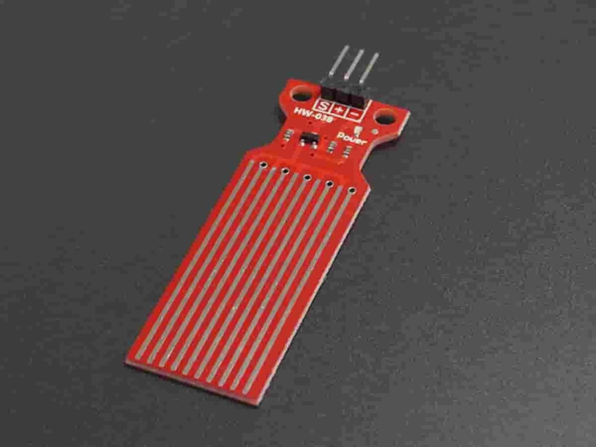
- The above water level sensor is works based on concept of the variable resistance.
- It is made up of multiple parallel conductors that are exposed and function as a variable resistor, changing resistance in relation to the water level in the tank.
- When more of the sensor is submerged, conductivity increases and resistance decreases. also, when less of the sensor is submerged, conductivity decreases, and resistance increases.
- The sensor gives output voltage proportional to the level of submerged it in the water.
Water level Sensor Pin Diagram:
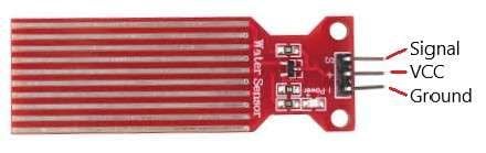
Water level Sensor Pin Description:
- S: is an analog output.
- VCC: The Supply voltage Pin is 3.3v to 5v.
- GND: is simply a ground connection.
Water level Sensor Interfacing with ESP32
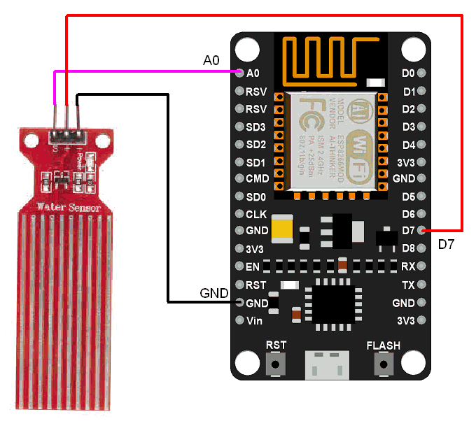
- The above sensor vcc pin is connected to the GPIO4 Pin, it will turn on only when taking the reading to reduce the corrosion.
.jpg)
ESP32 Pin Connection details for Water Level Sensor
| ESP32 Pins | Water Level Sensor Pins |
| A0 | S (Signal) |
| GPIO4 | Supply VCC |
| GND | GND |
Water level Sensor Code for ESP32 using Arduino IDE
#define sensorPower 4
#define sensorPin A0
int val = 0;

void setup() {
  pinMode(sensorPower, OUTPUT);
  digitalWrite(sensorPower, LOW);
  Serial.begin(9600);
}

void loop() {
  digitalWrite(sensorPower, HIGH);
  delay(10);
  val = analogRead(sensorPin);
  digitalWrite(sensorPower, LOW);
  Serial.print("Water level: ");
  Serial.println(val);
  delay(1000);
}
Let’s Understand the code
#define sensorPower 4
#define sensorPin A0
int val = 0;
This code is used to read the water level from a water level sensor connected to the analog pin A0 of an ESP32 board.
The water level sensor requires power to operate, so a digital pin G4 of the ESP32 board is used to provide power to the sensor.
The code defines the sensorPower pin as G4 and the sensorPin as A0 using the #define statement.
In the setup function,
pinMode(sensorPower, OUTPUT);
digitalWrite(sensorPower, LOW);
In the setup function, the sensorPower pin is set as an output pin using pinMode() function and the digitalWrite() function is used to set its initial value to LOW.
Serial.begin(9600);The Serial communication is initiated with a baud rate of 9600 using the Serial.begin() function.
In the loop function,
digitalWrite(sensorPower, HIGH);In the loop function, the digitalWrite() function is used to provide power to the water level sensor by setting the sensorPower pin to HIGH.
delay(10);Then, there is a delay of 10 milliseconds to allow the sensor to stabilize.
val = analogRead(sensorPin);The analogRead() function is used to read the voltage value from the sensor connected to the A0 pin of the ESP32 board, and the value is stored in the val variable.
digitalWrite(sensorPower, LOW);After that, the sensorPower pin is set to LOW to turn off the power supply to the sensor.
Serial.print("Water level: ");
Serial.println(val);
The water level reading is then printed to the Serial Monitor using the Serial.print() and Serial.println() functions.
delay(1000);The delay() function is used to wait for 1 second before the next reading is taken.
Downloads |
||
|---|---|---|
|
|
Water Level Sensor Code for ESP32 | Download |