Introduction
Pulse Width Modulation (PWM) is a technique by which the width of a pulse is varied while keeping the frequency of the wave constant. It is a method for generating an analog signal using a digital source.

A PWM signal consists of two main components that define its behavior: a duty cycle and a frequency.
Duty Cycle of Signal
A period of a pulse consists of an ON cycle (3.3V) and an OFF cycle (0V). The fraction for which the signal is ON over a period is known as a duty cycle.
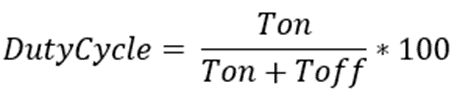
E.g. A pulse with a period of 10ms will remain ON (high) for 2ms. Therefore, the duty cycle will be
D = 2ms / 10ms = 20%
Through the PWM technique, we can control the power delivered to the load by using the ON-OFF signal. The PWM signals can be used to control the speed of DC motors and to change the intensity of the LED.
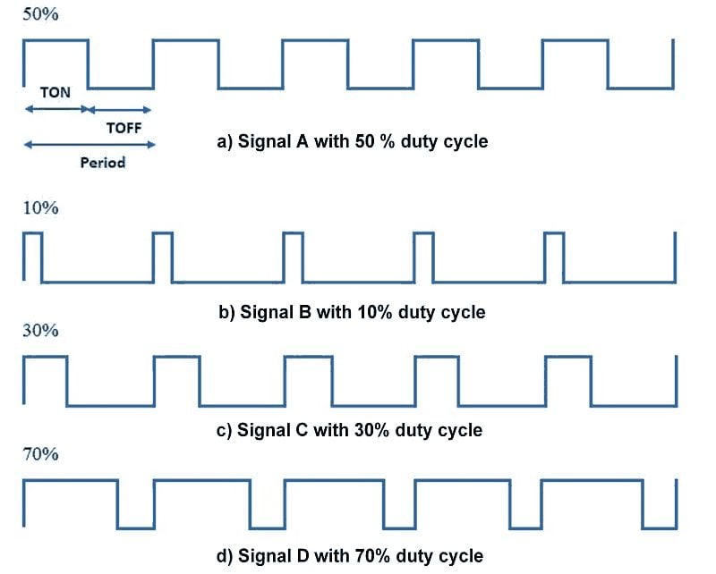
Pulse Width Modulated signals with different duty cycles are shown below
Now, let’s see PWM in ESP32.
PWM Pins of ESP32
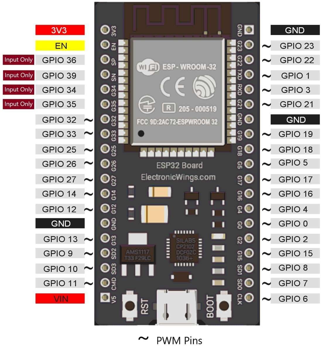
ESP32 Wroom module has 28, 0 to 16-bit PWM channels. Pins with the symbol ‘~’ represent that it has PWM support. These PWM pins are shown below image.
Arduino Functions for PWM
analogWrite (pin, duty cycle)
It is used to generate PWM or output analog values to a specified PWM channel.
pin – pin on which we want to generate PWM or analog signal.
duty cycle – it lies in between 0 (0%, always off) – 255 (100%, always on).
e.g. analogWrite (3, 127); //generates PWM of 50% duty cycleLED Fading using ESP32 PWM
Let’s create a small application in which LED will fade continuously. This LED fading application is used for decoration at functions and festivals.
Interfacing Diagram
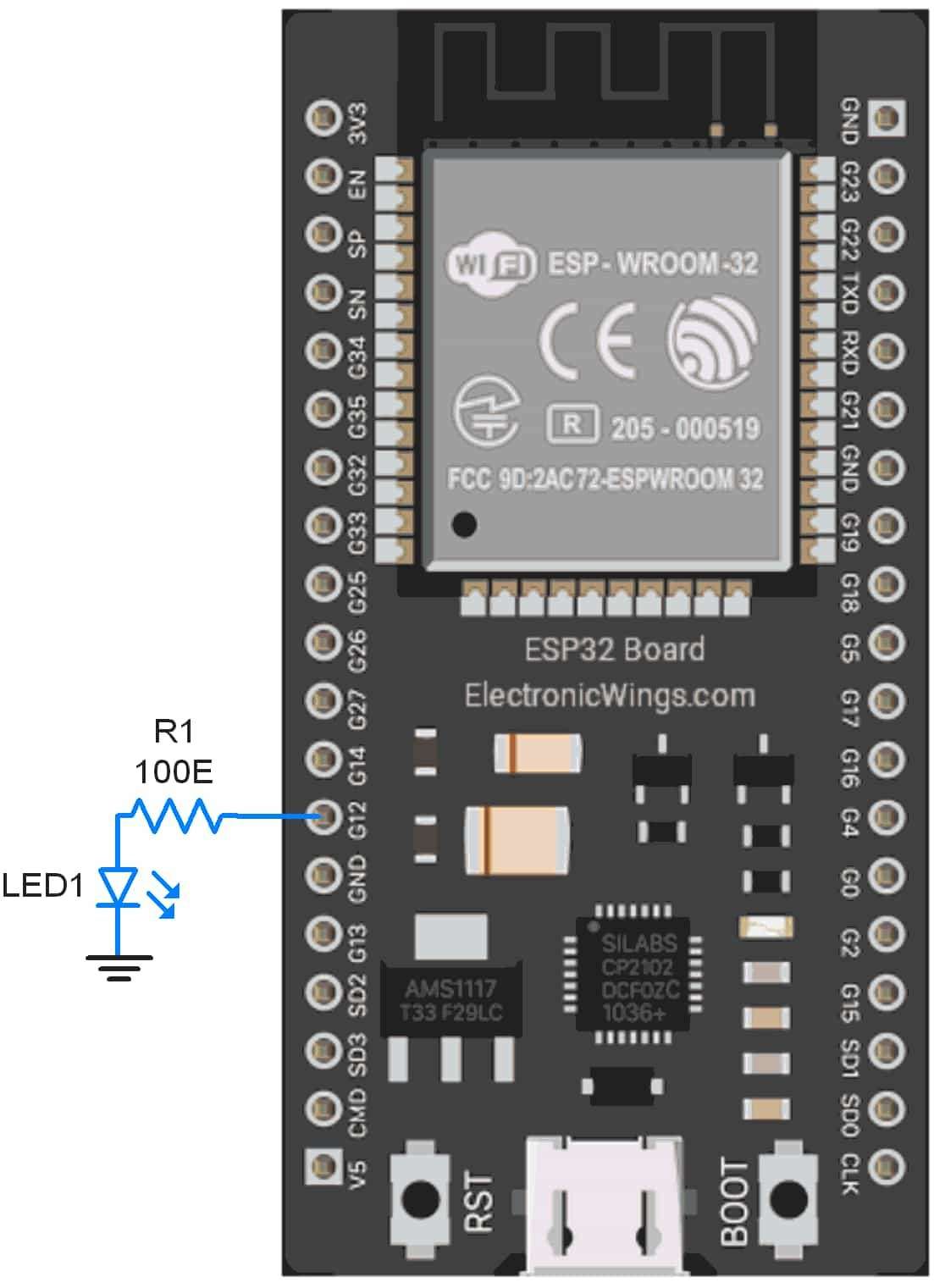
Sketch for LED fading using ESP32 PWM
int led =12;           // the PWM pin the LED is attached to
int brightness = 0;    // how bright the LED is
int fadeAmount = 5;    // how many points to fade the LED by

void setup() {
 pinMode(led, OUTPUT); // declare pwm pin to be an output:
}

void loop() {
 analogWrite(led, brightness); // set the brightness of led

 // change the brightness for next time through the loop:
 brightness = brightness + fadeAmount;

 // reverse the direction of the fading at the ends of the fade:
 if (brightness <= 0 || brightness >= 255) {
   fadeAmount = -fadeAmount;
 }
 delay(30);  // wait for 30 milliseconds to see the dimming effect
}
Output
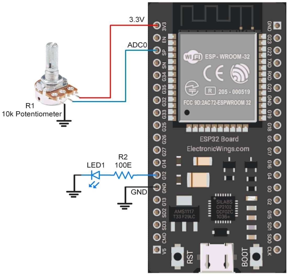
Control LED Brightness using Potentiometer
Let’s build an application in which we will control the brightness of LED using ESP32 by varying the potentiometer knob. So, when we rotate the knob of the potentiometer, the ADC of ESP32 will read this analog signal. Then we will generate PWM signal proportional to the analog signal.
Interfacing Diagram
Sketch for controlling LED Brightness
int ledPin = 12;      // LED connected to digital pin D12
int analogPin = A0;  // potentiometer connected to analog pin A0
int val = 0;         // variable to store the read value

void setup()
{
  pinMode(ledPin, OUTPUT);   // sets the pin as output
}

void loop()
{
  val = analogRead(analogPin); // read the input pin
  analogWrite(ledPin, val / 16);// analogRead values go from 0 to 4095, analogWrite values from 0 to 255
}
ESP32 LEDC APIs with Arduino IDE
Dedicated ESP32 PWM functions: Allows much more flexibility in PWM generation.
Here is a list of all the LEDC APIs exposed by the driver. These functions are written for the Arduino IDE port of ESP32.
ledcSetup(channel, frequency, resolution_bits)
This function is used to setup the channel, frequency, and resolution bit for LEDC.
Channel: Channel number where you want to configure
Frequency: Set the PWM frequency
Resolution_bits: Set the resolution in the range of 0 to 20 bits for the LEDC channel.
e.g. ledcSetup(0, 5000, 8);
ledcAttachPin(pin, channel)
This function is used to attach the pin to the LEDC channel.
pin: pin number which we want to generate LEDC
channel: set the LEDC channel number.
e.g. ledcAttachPin(16, 0);
ledcWrite(channel, dutycycle)
This function is used to define the duty cycle to the LEDC channel.
channel: Set the LEDC channel number.
dutycycle: Set the duty cycle for the selected LEDC channel
e.g. ledcWrite(0, 125);
ledcRead(channel)
This function is used to read the configured LEDC channel.
channel: Set the LEDC channel number which you want to get the configuration
e.g. ledcRead(0);
ledcWriteTone(channel, frequency)
This function is used to set the 50% PWM tone to the selected frequency
channel: Set the LEDC channel number.
frequency: Set the frequency of PWM
e.g. ledcWriteTone(0, 800);
ledcWriteNote(channel, note, octave)
This function is used to setup the LEDC channel to a specific note.
channel: Set the LEDC channel number.
Note: set the note from the below chart
| NOTE_C | NOTE_Cs | NOTE_D | NOTE_Eb | NOTE_E | NOTE_F |
| NOTE_Fs | NOTE_G | NOTE_Gs | NOTE_A | NOTE_Bb | NOTE_B |
octave: select octave for note
e.g. ledcWriteNote(0, NOTE_C, 4);
ledcReadFreq(channel)
This function is used to read the configured frequency for the selected LEDC channel.
channel: Set the LEDC channel number.
e.g. ledcReadFreq(0);
ledcDetachPin(pin)
This function is used to detach the pin from the LEDC channel.
pin: set the pin to detach from LEDC
e.g. ledcDetachPin(16);
Example using LEDC function
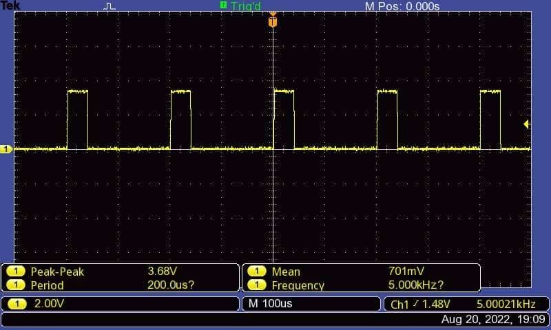
Now let’s take a simple example to generate the PWM waveform using the LEDC APIs function
Sketch for PWM using LEDC functions for ESP32
/*
  ESP32 PWM Generation using LEDC functions
  http:://www.electronicwings.com
*/

const int ledPin = 12;      // the PWM pin the LED is attached to
const int freq = 5000;      // set the frequency for 5kHz
const int ledChannel = 0;   // set the PWM channel
const int resolution = 8;   // set PWM resolution

void setup(){
  ledcSetup(ledChannel, freq, resolution);  // define the PWM Setup
  ledcAttachPin(ledPin, ledChannel);
}

void loop(){
    ledcWrite(ledChannel, 50);        // set the Duty cycle to 50 out of 255
    delay(15);                       // Wait for 15 mS
}
Output
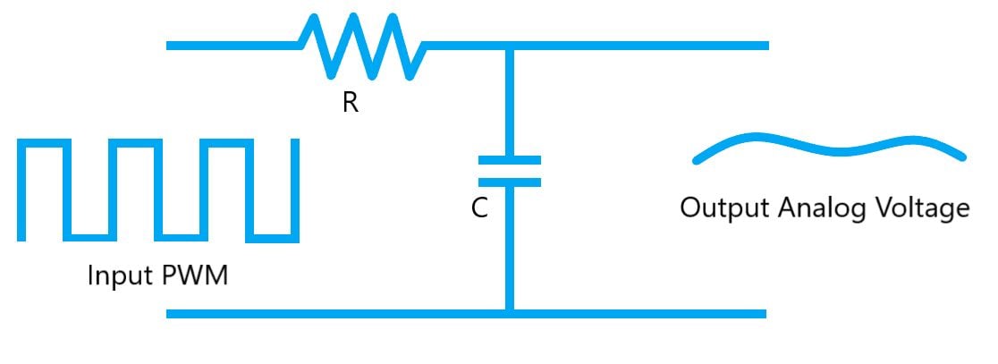
PWM Signal to Equivalent Voltage Output
The frequency of a signal determines how fast the PWM completes a cycle (i.e. 1000 Hz would be 1000 cycles per second) which means how fast it switches between ON (high) and OFF (low) states.
By repeating this ON-OFF pattern at a fast-enough rate, and with a certain duty cycle, with Low Pass RC-filter at the output, it will behave like a constant voltage, where voltage can be changed by varying the PWM Duty cycle.
Example: If we want to create a 2V analog signal for a given digital source that can be either high (on) at 3.3V, or low (off) at 0V, we can use PWM with a duty cycle of 60.6%. It will provide an output of 3.3V for 60.6% of the time.
Components Used |
||
|---|---|---|
| ESP32 WROOM WiFi Development Tools - 802.11 ESP32 General Development Kit, embeds ESP32-WROOM-32E, 4MB flash. |
X 1 | |