Introduction
- When we want to interface one key to the microcontroller then it needs one GPIO pin. But when we want to interface many keys like 9, 12 or 16 etc., then it may acquire all GPIO pins of microcontroller.
- To save some GPIO pins of microcontroller, we can use matrix keypad. Matrix keypad is nothing but keys arrange in row and column.
- E.g. if we want to interface 16 keys to the microcontroller then we require 16 GPIO pins but if we use matrix 4x4 keypad then we require only 8 GPIO pins of microcontroller.
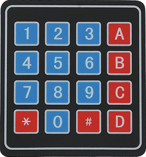
4x4 Keypad Matrix Structure
Keyboards are organized in a matrix of rows and columns. When a key is pressed, a row and a column make a contact Otherwise; there is no connection between rows and columns.
Specification of 4x4 keypad
- Key layout: 4 rows x 4 columns (16 keys total)
- Key Type: Membrane
- Operating voltage: 3V - 5V DC
- Interface: 8 digital pins (4 for rows, 4 for columns)
- Connector: Female 2.54mm Pitch
Application of 4x4 keypad
4x4 keypads are widely used in various applications, here are a few examples:
Access Control Systems, Security Systems, Data Entry Systems, Industrial Control Systems, Robotics, Electronic projects, etc.
Keypad Matrix Working
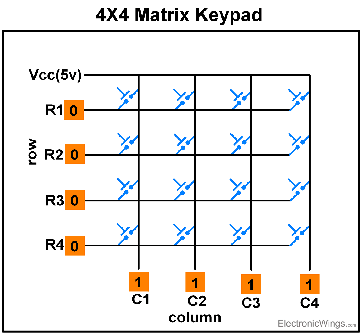
Scanning of Keys
To detect a pressed key, the microcontroller grounds all rows by providing 0 to the output latch, and then it reads the columns shown in above fig.
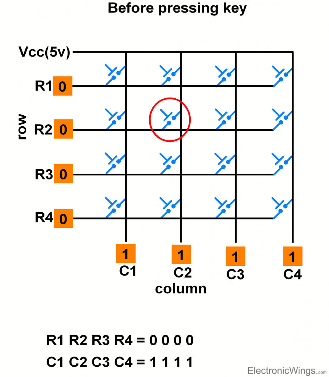
- If the data read from columns is = 1111, no key has been pressed shown in above fig. and the process continues till key press is detected.
- Now, consider highlighted key in above fig. is pressed. After pressing key, it makes contact of row with column shown below.
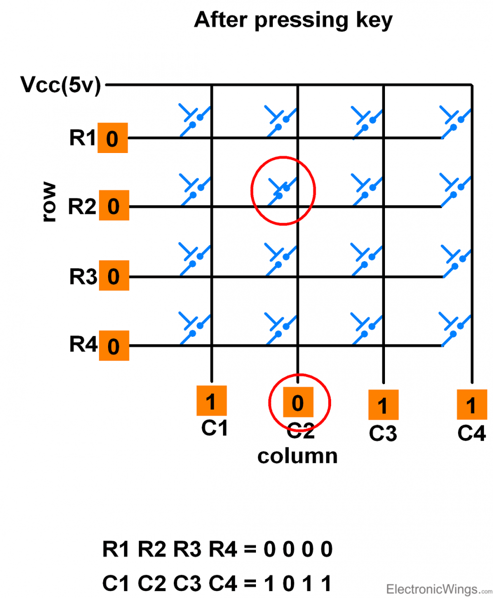
- If one of the column bits has a zero, this means that a key press has occurred.
- For example, if C1:C4 = 1011, this means that a key in the C2 column has been pressed.
- After detecting a key press, microcontroller will go through the process of identifying the key.
Process of Identifying the Key
Starting from the top row, the microcontroller will ground it by providing a low to row R1 only.
- Now read the columns, if the data read is all 1s, no key in that row is pressed and the process continues for the next row.
- So, now ground the next row, R2. Read the columns, check for any zero and this process continues until the row is identified.
- E.g. In the above case, we will get row 2 in which column is not equal to 1111.
- So, after identification of the row in which the key has been pressed we can easily find out the key by row and column value.
Keypad Interfacing using One wire
It is possible to interface Keypad of any size with just one Analog pin. It is based on voltage divider network.
E.g. 4x4 keypad interfacing with one wire as shown below.
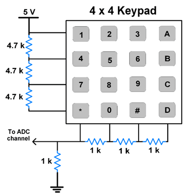
Note: Resistor value combinations can be different.
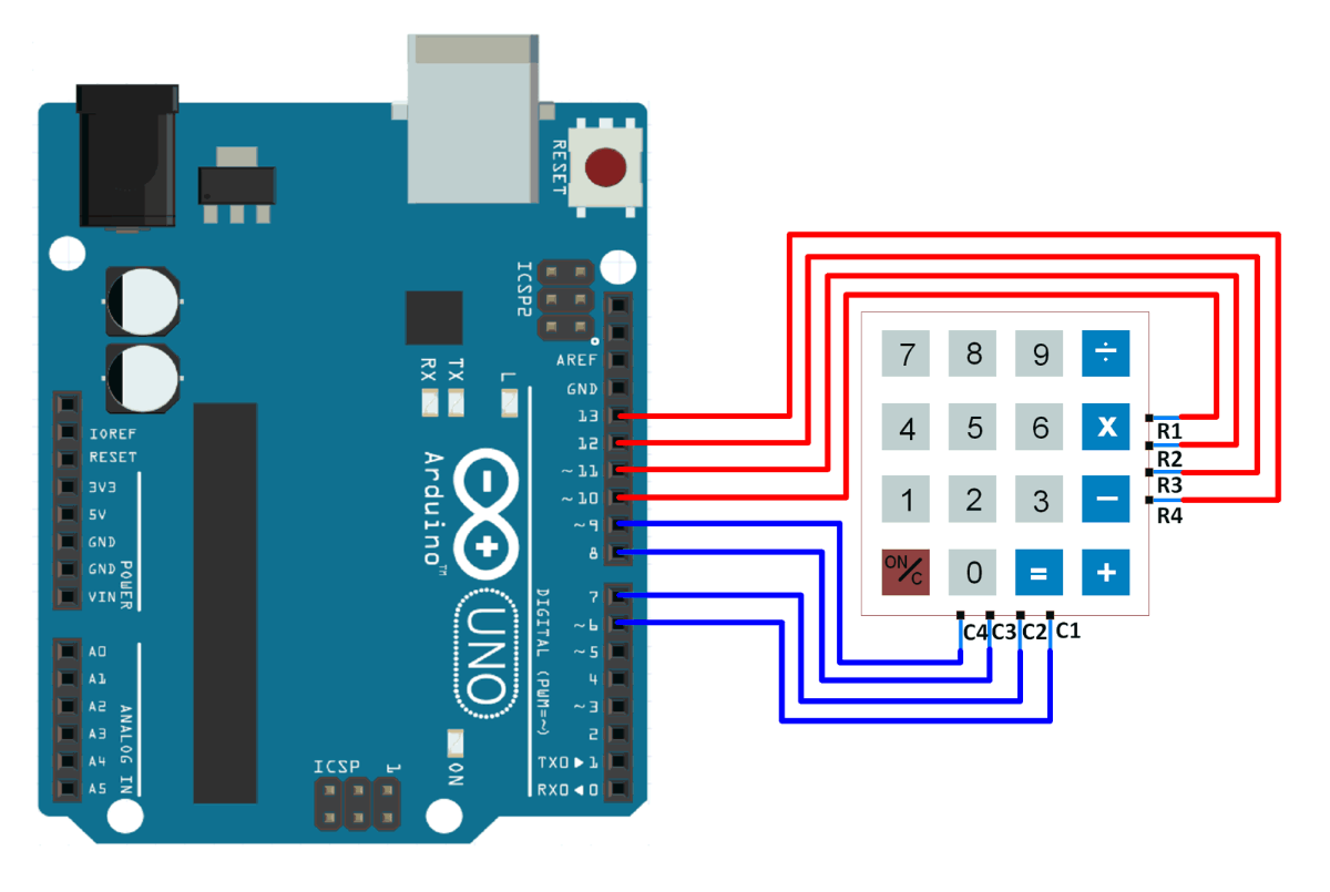
4x4 keypad interfacing with Arduino
4x4 keypad Code for Arduino
const byte ROWS = 4; //four rows
const byte COLS = 4; //four columns
char keys[ROWS][COLS] = {
  {'1','2','3','A'},
  {'4','5','6','B'},
  {'7','8','9','C'},
  {'*','0','#','D'}
};
byte rowPins[ROWS] = {13, 12, 11, 10}; //connect to the row pinouts of the keypad
byte colPins[COLS] = {9, 8, 7, 6}; //connect to the column pinouts of the keypad

void setup() {
  for (byte i = 0; i < ROWS; i++) {
    pinMode(rowPins[i], INPUT_PULLUP);
  }
  for (byte i = 0; i < COLS; i++) {
    pinMode(colPins[i], OUTPUT);
  }
  Serial.begin(9600); //initialize serial communication
}

void loop() {
  char key = getKey();
  if (key) {
    Serial.println(key);
  }
}

char getKey() {
  for (byte c = 0; c < COLS; c++) {
    digitalWrite(colPins[c], LOW);
    for (byte r = 0; r < ROWS; r++) {
      if (digitalRead(rowPins[r]) == LOW) {
        digitalWrite(colPins[c], HIGH);
        delay(50);
        return keys[r][c];
      }
    }
    digitalWrite(colPins[c], HIGH);
  }
  return 0;
}
The output of this code depends on which keys are pressed on the keypad. When a key is pressed, its corresponding character is printed to the serial monitor. If no key is pressed, nothing is printed.
To know more about 4x4 keypad using Arduino refer to this link
Examples of 4x4 Keypad interfacing
Components Used |
||
|---|---|---|
| 4x4 Keypad Module Keypad is an input device which is generally used in applications such as calculator, ATM machines, computer etc. |
X 1 | |