Introduction
MPU6050 sensor module is complete 6-axis Motion Tracking Device. It combines 3-axis Gyroscope, 3-axis Accelerometer and Digital Motion Processor all in small package. Also, it has additional feature of on-chip Temperature sensor. It has I2C bus interface to communicate with the microcontrollers.
It has Auxiliary I2C bus to communicate with other sensor devices like 3-axis Magnetometer, Pressure sensor etc.
If 3-axis Magnetometer is connected to auxiliary I2C bus, then MPU6050 can provide complete 9-axis Motion Fusion output.
Let’s see MPU6050 inside sensors.
3-Axis Gyroscope
The MPU6050 consist of 3-axis Gyroscope with Micro Electro Mechanical System(MEMS) technology. It is used to detect rotational velocity along the X, Y, Z axes as shown in below figure.
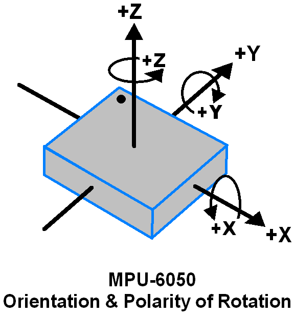
- When the gyros are rotated about any of the sense axes, the Coriolis Effect causes a vibration that is detected by a MEM inside MPU6050.
- The resulting signal is amplified, demodulated, and filtered to produce a voltage that is proportional to the angular rate.
- This voltage is digitized using 16-bit ADC to sample each axis.
- The full-scale range of output are +/- 250, +/- 500, +/- 1000, +/- 2000.
- It measures the angular velocity along each axis in degree per second unit.
3-Axis Accelerometer
The MPU6050 consist 3-axis Accelerometer with Micro Electro Mechanical (MEMs) technology. It used to detect angle of tilt or inclination along the X, Y and Z axes as shown in below figure.
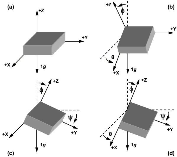
- Acceleration along the axes deflects the movable mass.
- This displacement of moving plate (mass) unbalances the differential capacitor which results in sensor output. Output amplitude is proportional to acceleration.
- 16-bit ADC is used to get digitized output.
- The full-scale range of acceleration are +/- 2g, +/- 4g, +/- 8g, +/- 16g.
- It measured in g (gravity force) unit.
- When device placed on flat surface it will measure 0g on X and Y axis and +1g on Z axis.
DMP (Digital Motion Processor)
The embedded Digital Motion Processor (DMP) is used to compute motion processing algorithms. It takes data from gyroscope, accelerometer and additional 3rd party sensor such as magnetometer and processes the data. It provides motion data like roll, pitch, yaw angles, landscape and portrait sense etc. It minimizes the processes of host in computing motion data. The resulting data can be read from DMP registers.
On-chip Temperature Sensor
On-chip temperature sensor output is digitized using ADC. The reading from temperature sensor can be read from sensor data register.
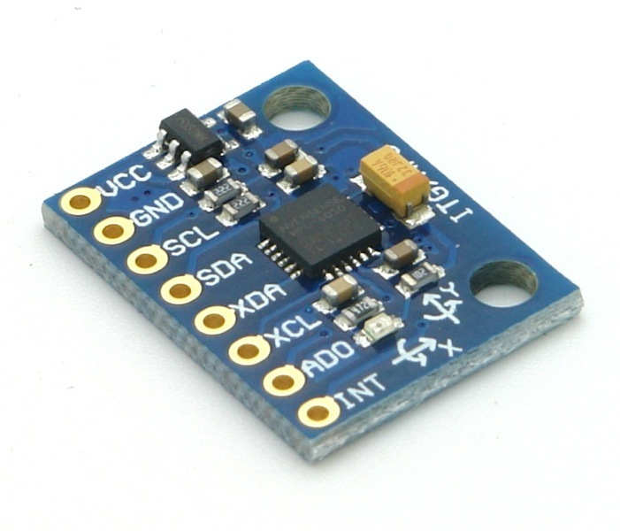
MPU6050 Module Pinout
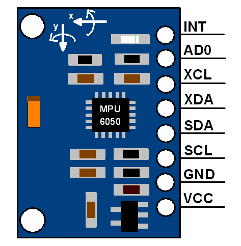
MPU6050 Pin Description
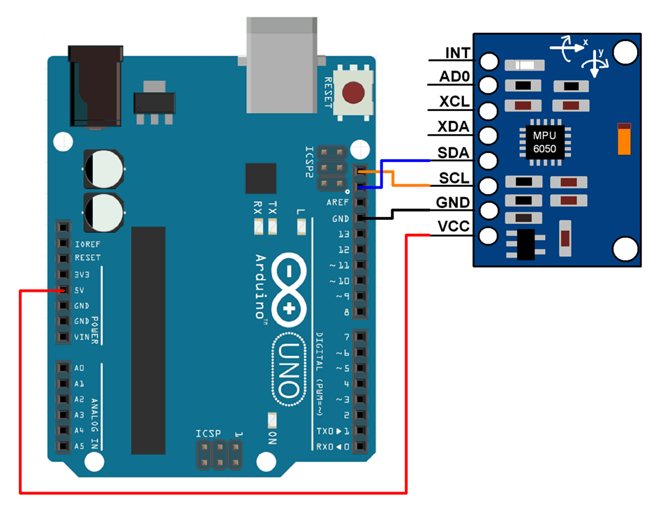
The MPU-6050 module has 8 pins,
- INT: Interrupt digital output pin.
- AD0: I2C Slave Address LSB pin. This is 0th bit in 7-bit slave address of device. If connected to VCC then it is read as logic one and slave address changes.
- XCL: Auxiliary Serial Clock pin. This pin is used to connect other I2C interface enabled sensors SCL pin to MPU-6050.
- XDA: Auxiliary Serial Data pin. This pin is used to connect other I2C interface enabled sensors SDA pin to MPU-6050.
- SCL: Serial Clock pin. Connect this pin to microcontrollers SCL pin.
- SDA: Serial Data pin. Connect this pin to microcontrollers SDA pin.
- GND: Ground pin. Connect this pin to ground connection.
- VCC: Power supply pin. Connect this pin to +5V DC supply.
- MPU-6050 module has Slave address (When AD0 = 0, i.e. it is not connected to Vcc) as,
- Slave Write address(SLA+W): 0xD0
- Slave Read address(SLA+R): 0xD1
MPU-6050 has various registers to control and configure its mode of operation. So, kindly go through MPU-6050 datasheet and MPU-6050 Register Map.
Specification of MPU6050 Sensor
Gyroscope:
- 3-axis sensing with a full-scale range of ±250, ±500, ±1000, or ±2000 degrees per second (dps)
- Sensitivity of 131, 65.5, 32.8, or 16.4 LSBs per dps
- Output data rate (ODR) range of 8kHz to 1.25Hz
Accelerometer:
- 3-axis sensing with a full-scale range of ±2g, ±4g, ±8g, or ±16g
- Sensitivity of 16384, 8192, 4096, or 2048 LSBs per g
- ODR range of 8kHz to 1.25Hz
- Temperature Sensor:
- Operating range of -40°C to +85°C
- Sensitivity of 340 LSBs per degree Celsius
- Accuracy of ±3°C
Supply Voltage:
- Operating voltage range of 2.375V to 3.46V for the MPU-6050, and 2.375V to 5.5V for the MPU-6050A
- Communication Interface:
- I2C serial interface with a maximum clock frequency of 400kHz
- 8-bit and 16-bit register access modes
Other Features:
- Digital Motion Processor (DMP) for complex motion processing
- On-chip 16-bit ADCs for accurate analog-to-digital conversion
- Programmable digital filters for improved noise performance
- Interrupts for triggering events based on specific motion conditions
- Low-power consumption (3.9mA for full operation)
Calculations
Note that gyroscope and accelerometer sensor data of MPU6050 module consists of 16-bit raw data in 2’s complement form.
Temperature sensor data of MPU6050 module consists of 16-bit data (not in 2’s complement form).
Now suppose we have selected,
- Accelerometer full scale range of +/- 2g with Sensitivity Scale Factor of 16,384 LSB(Count)/g.
- Gyroscope full scale range of +/- 250 °/s with Sensitivity Scale Factor of 131 LSB (Count)/°/s.
then,
To get sensor raw data, we need to first perform 2’s complement on sensor data of Accelerometer and gyroscope.
After getting sensor raw data we can calculate acceleration and angular velocity by dividing sensor raw data with their sensitivity scale factor as follows,
Accelerometer values in g (g force)
Acceleration along the X axis = (Accelerometer X axis raw data/16384) g.
Acceleration along the Y axis = (Accelerometer Y axis raw data/16384) g.
Acceleration along the Z axis = (Accelerometer Z axis raw data/16384) g.
Gyroscope values in °/s (degree per second)
Angular velocity along the X axis = (Gyroscope X axis raw data/131) °/s.
Angular velocity along the Y axis = (Gyroscope Y axis raw data/131) °/s.
Angular velocity along the Z axis = (Gyroscope Z axis raw data/131) °/s.
Temperature value in °/c (degree per Celsius)
Temperature in degrees C = ((temperature sensor data)/340 + 36.53) °/c.
For example,
Suppose, after 2’ complement we get accelerometer X axes raw value = +15454
Then Ax = +15454/16384 = 0.94 g.
Alternate options for MPU6050
MPU9250: This sensor module combines a 3-axis accelerometer, 3-axis gyroscope, and 3-axis magnetometer in a single package.
LSM6DS3: This sensor module also combines a 3-axis accelerometer and 3-axis gyroscope, but has a lower power consumption and smaller size than the MPU6050.
ADXL345: This sensor module offers a 3-axis accelerometer with a full-scale range of ±2g, ±4g, ±8g, or ±16g.
BNO055: This sensor module offers a 3-axis accelerometer, 3-axis gyroscope, and 3-axis magnetometer, along with a built-in processor for fusion of sensor data.
MPU6050 interfacing with Arduino
Here, we will be using Korneliusz Jarzebski’s MPU6050 library from GitHub.
Download this library from here.
MPU6050 Code for Arduino Uno
/*
    MPU6050 Triple Axis Gyroscope & Accelerometer. Simple Accelerometer Example.
    Read more: http://www.jarzebski.pl/arduino/czujniki-i-sensory/3-osiowy-zyroskop-i-akcelerometr-mpu6050.html
    GIT: https://github.com/jarzebski/Arduino-MPU6050
    Web: http://www.jarzebski.pl
    (c) 2014 by Korneliusz Jarzebski
*/

#include<Wire.h>
#include<MPU6050.h>

MPU6050 mpu;

void setup() {
 Serial.begin(115200);

 Serial.println("Initialize MPU6050");

 while(!mpu.begin(MPU6050_SCALE_2000DPS, MPU6050_RANGE_2G)){
   Serial.println("Could not find a valid MPU6050 sensor, check wiring!");
   delay(500);
 }

  // If you want, you can set accelerometer offsets
  // mpu.setAccelOffsetX();
  // mpu.setAccelOffsetY();
  // mpu.setAccelOffsetZ();

 checkSettings();
}

void checkSettings()
{
 Serial.println();

 Serial.print(" * Sleep Mode:            ");
 Serial.println(mpu.getSleepEnabled() ? "Enabled" : "Disabled");

 Serial.print(" * Clock Source:          ");
  switch(mpu.getClockSource())
  {
    case MPU6050_CLOCK_KEEP_RESET:     Serial.println("Stops the clock and keeps the timing generator in reset"); break;
    case MPU6050_CLOCK_EXTERNAL_19MHZ: Serial.println("PLL with external 19.2MHz reference"); break;
    case MPU6050_CLOCK_EXTERNAL_32KHZ: Serial.println("PLL with external 32.768kHz reference"); break;
    case MPU6050_CLOCK_PLL_ZGYRO:      Serial.println("PLL with Z axis gyroscope reference"); break;
    case MPU6050_CLOCK_PLL_YGYRO:      Serial.println("PLL with Y axis gyroscope reference"); break;
    case MPU6050_CLOCK_PLL_XGYRO:      Serial.println("PLL with X axis gyroscope reference"); break;
    case MPU6050_CLOCK_INTERNAL_8MHZ:  Serial.println("Internal 8MHz oscillator"); break;
  }

 Serial.print(" * Accelerometer:         ");
 switch(mpu.getRange()){
    case MPU6050_RANGE_16G:            Serial.println("+/- 16 g"); break;
    case MPU6050_RANGE_8G:             Serial.println("+/- 8 g"); break;
    case MPU6050_RANGE_4G:             Serial.println("+/- 4 g"); break;
    case MPU6050_RANGE_2G:             Serial.println("+/- 2 g"); break;
 }

 Serial.print(" * Accelerometer offsets: ");
 Serial.print(mpu.getAccelOffsetX());
 Serial.print(" / ");
 Serial.print(mpu.getAccelOffsetY());
 Serial.print(" / ");
 Serial.println(mpu.getAccelOffsetZ());

 Serial.println();
}

void loop() {
 	Vector rawAccel = mpu.readRawAccel();
 	Vector normAccel = mpu.readNormalizeAccel();

 	Serial.print(" Xraw = ");
 	Serial.print(rawAccel.XAxis);
 	Serial.print(" Yraw = ");
 	Serial.print(rawAccel.YAxis);
 	Serial.print(" Zraw = ");

 	Serial.println(rawAccel.ZAxis);
 	Serial.print(" Xnorm = ");
 	Serial.print(normAccel.XAxis);
 	Serial.print(" Ynorm = ");
 	Serial.print(normAccel.YAxis);
 	Serial.print(" Znorm = ");
 	Serial.println(normAccel.ZAxis);

 	delay(10);
}
The output on the serial window will display the X, Y, and Z raw readings from the accelerometer followed by their normalized values. These values will be continuously displayed on the serial monitor with a delay of 10 milliseconds between each reading.
To know more about MPU6050 Sensor using Arduino refer to this link
Examples of MPU6050 interfacing
Components Used |
||
|---|---|---|
| MPU6050 Gyroscope and Accelerometer MPU6050 (Gyroscope + Accelerometer + Temperature) is a combination of 3-axis Gyroscope, 3-axis Accelerometer and Temperature sensor with on-chip Digital Motion Processor (DMP). It is used in mobile devices, motion enabled games, 3D mice, Gesture (motion command) technology etc |
X 1 | |