Introduction
- Real Time Clock (RTC) is used to track the current time and date. It is generally used in computers, laptops, mobiles, embedded system applications devices, etc.
- In many embedded systems, we need to put time stamps while logging data i.e. sensor values, GPS coordinates, etc. For getting timestamps, we need to use RTC (Real Time Clock).
- Some microcontrollers like LPC2148, LPC1768, etc., have on-chip RTC. But in other microcontrollers like PIC, and ATmega16/32, do not have on-chip RTC. So, we should use an external RTC chip
- There are different types of ICs used for RTC like DS1307, DS12C887, etc. In this section, we will see DS1307.
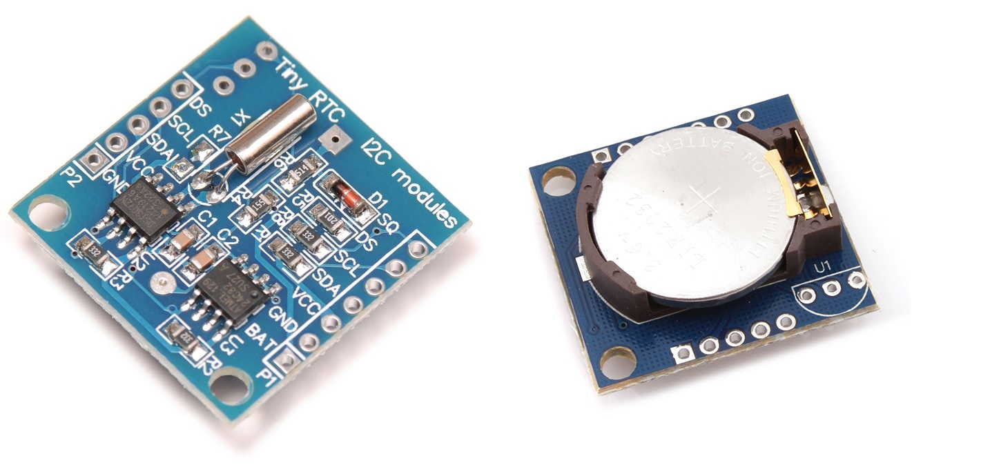
Pinout of DS1307 RTC Module
DS1307 RTC Module Pin Description
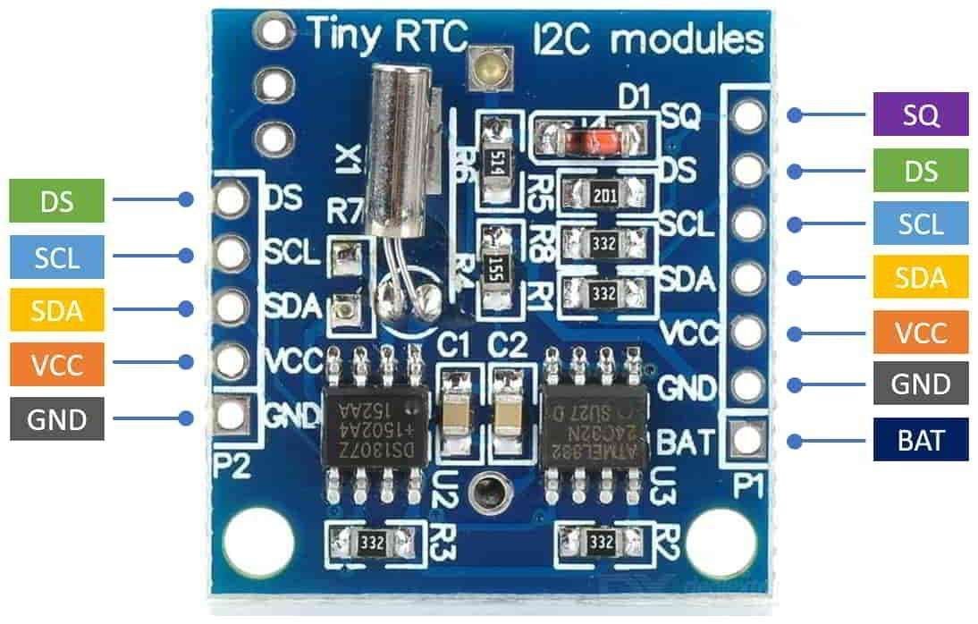
The DS1307 RTC (Real-Time Clock) module typically has 8 pins. The pin description is as follows:
- VCC: Power supply pin, usually connected to 5V or 3.3V
- GND: Ground pin
- SDA: I2C data pin, connected to the microcontroller's SDA pin.
- SCL: I2C clock pin, connected to the microcontroller's SCL pin.
- SQW: Square wave output pin, used to output a square wave signal with a frequency of 1Hz, 4kHz, 8kHz, or 32kHz.
RTC DS1307 Circuit Diagram Diagram
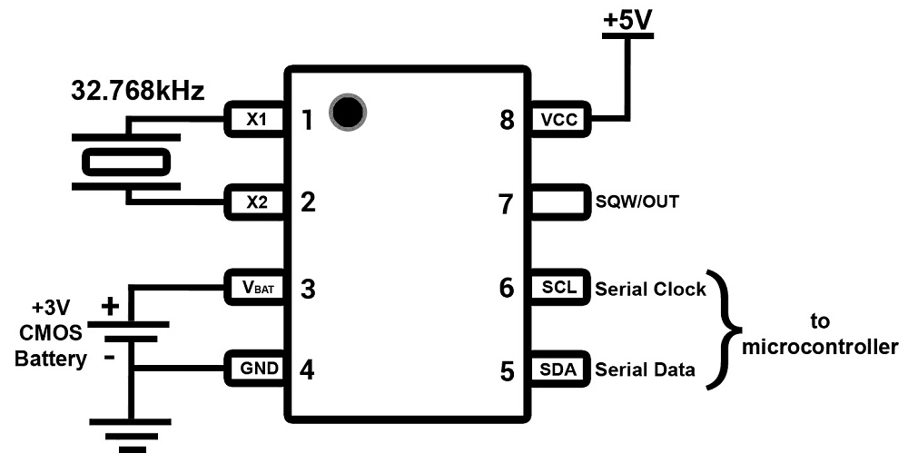
- The RTC DS1307 is 8 pin IC, shown in above fig.
- The RTC DS1307 uses external crystal of frequency 32.768 kHz, so we need to connect crystal with 32.768 kHz to X1 and X2 pin.
- Connect 3 Volt CMOS battery to Vbat pin. RTC DS1307 has inbuilt mechanism to detect 5 volt VCC, if external 5 volt VCC is not there, then it takes the supply from 3 volt CMOS battery.
- The SDA (Serial Data) and SCL (Serial Clock) pins are I2C serial communication pins which are used to connect with microcontroller’s I2C pins.
- SQW/OUT pin is square wave output driver. The SQW/OUT pin outputs one of four square-wave frequencies 1Hz, 4kHz, 8kHz, 32kHz by setting internal register bits.
Generally, while using RTC (Real Time Clock) first time, we need to set current time and date in RTC. Then RTC keeps updating these values in seconds. In RTC DS1307, we can set this time and date in the Timekeeper Register. After setting time and date value, RTC DS1307 keeps updating it in seconds so we will get updated time later.
Specification of DS1307
- Operating Voltage: 5V DC
- Operating Temperature: -55°C to +125°C
- Accuracy: ±2ppm at 25°C
- Clock Operating Frequency: 32.768KHz
- I2C Interface: Standard I2C interface, with 7-bit addressing
- SRAM Memory: 56 bytes of battery-backed SRAM
- Battery Backup: 3V Lithium Coin Cell or equivalent
- Operating Current: 55uA (at 3V battery)
- RTC Operating Current: Max. 200uA
- I2C Communication Speed: 100KHz and 400KHz
- Real-Time Clock Counter: Hours, Minutes, Seconds, Day, Date, Month and Year
Timekeeper Registers
- The content of Timekeeper registers is in BCD (Binary Coded Decimal value) format.
- There are total eight registers in timekeeper register for setting seconds, Minutes, Hours, Day, Date, Month, year and control.
- Once we set the value of these registers, they will keep updating themselves, and we can read these registers to get updated values.
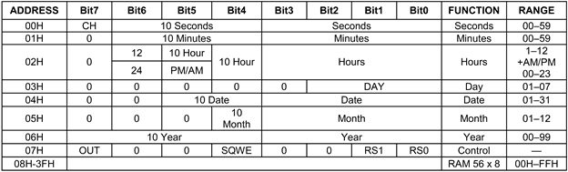
From datasheet
DS1307 I2C Address
Address - 00H:02H: Clock Registers
Address - 00H:
- In this register bit- 7 is CH bit, which is crystal oscillator enable / disable bit, when it is zero, the crystal oscillator is enabled otherwise oscillator is not enabled, so we always make this bit zero while using RTC.
- Other bits are used for read / write the second. As timekeeper register stores the value in BCD format, here Bit- 4 to Bit-6 stores the upper BCD digit of the seconds (value from 0 to 5), and Bit- 0 to Bit-3 stores lower BCD digit of the seconds (value from 0 to 9). As seconds’ value starts from 00 and ends at 59.
Address - 01H:
- This address is used to read / write minutes’ value.
- Upper BCD digit of minutes is stored in Bit-4 to Bit-6 and lower BCD digit is stored in Bit-0 to Bit- 3
Address - 02H:
- This address is used to read / write Hour.
- Clock can run in either 12Hr or 24Hr format.
- 12-hour format: To set 12-hour clock format, we need to set Bit- 6 to logic 1. In 12- hour clock format Bit-5 will indicate AM / PM, Logic 1 is for PM and Logic 0 is for AM. Bit-4 is indicated as 10 Hour, which is to store higher digit of hour value, which is 0 or 1 in case of 12-hour system. Bit-0 to Bit- 3 stores the value of lower digit of hour (value from 0 to 9).
- 24-hour Format: To set 24-hour clock format, we need to reset Bit- 6 to logic 0. Bit-4 and Bit- 5 are indicated as 10 Hour, which is to store higher digit of hour value, which is 0 to 2 in case of 24-hour system. Bit-0 to Bit- 3 stores the value of lower digit of hour (value from 0 to 9).
Address - 03H: 06H: Calendar Register
Address - 03H:
- This address isused to read /write day value from 1 to 7. Bit-0 to Bit-2 are used to read /write day value.
Address - 04H:
- This address isused to read/write the date value. Bit- 4 and Bit-5 are used to read / write upper digit value of date (value from 0 to 3). Bit- 0 to Bit-3 are used for lower digit of date value (value from 0 to 9).
Address - 05H:
- This address is used to read/write the month. Bit- 4 used for upper digit value of month that is 0 or 1. And Bit- 0 to Bit- 3 are used to store the lower digit value of the month (value from 0 to 9).
Address-06H:
- This address isused to read/write the year value. It provides only last two digits of year value. Bit- 0 to Bit- 3 stores lower digit, and Bit- 4 to Bit- 7 stores higher digit of the year.
Address-07H: Control Register

Bit 7 - OUT: Output
This controls the output level of pin SQW/OUT. When square wave output is disabled, SQWE bit is zero. So, logic level on SQW/OUT is high when this OUT bit is high, and zero when this OUT bit is zero.
Bit 4 – SQWE
To Enable / Disable square wave output on SQW / OUT pin
1 = Enable oscillator output
0 = Disable oscillator output
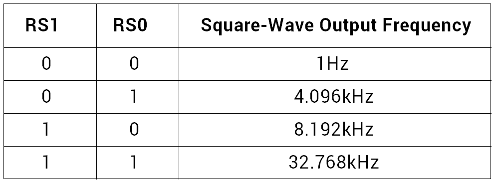
The frequency of square wave is depending on RS0 and RS1 bit.
Bit 0:1 - RS0 & RS1
Alternate options for DS1307
- PCF8563 RTC Module: This is a low power I2C RTC module that is pin-compatible with the DS1307 and has a similar function set.
- MCP7940N RTC Module: This is a low power I2C RTC module that has a small form factor and provides additional features such as a backup battery input, alarms, and SRAM.
- DS3231 RTC Module: This is a high precision I2C RTC module that provides a temperature-compensated oscillator and improved accuracy compared to the DS1307.
- DS1339 RTC Module: This is an I2C RTC module that provides improved accuracy and a battery-backup input, in a small form factor.
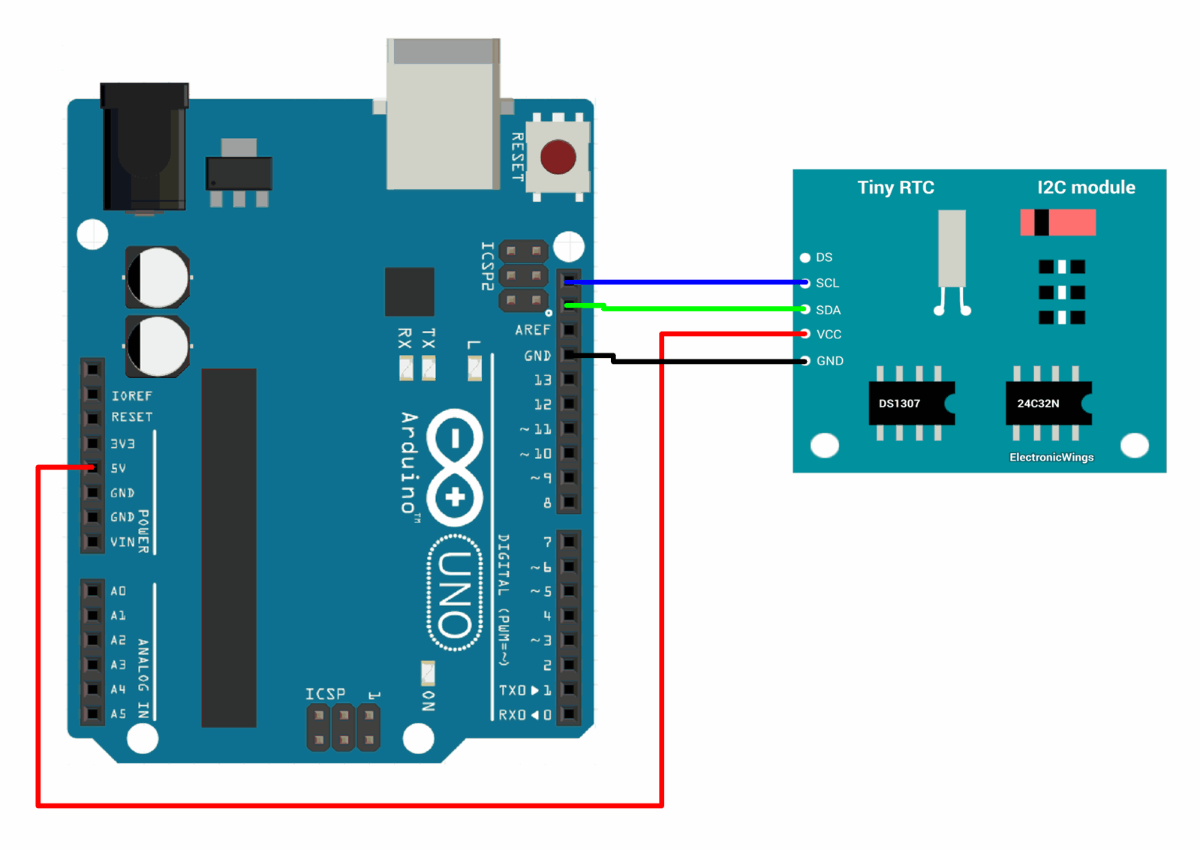
DS1307 RTC Module interfacing with Arduino
DS1307 RTC Module Code for Arduino
Programming Arduino to feed RTC with current date and time, and reading the date and time from the RTC.
Here, we will be using DS1307 library by Watterott from GitHub.
Download this library from here.
/*
  DS1307 RTC (Real-Time-Clock) Example

  Uno      A4 (SDA), A5 (SCL)
  Mega     20 (SDA), 21 (SCL)
  Leonardo  2 (SDA),  3 (SCL)
/*
  DS1307 RTC (Real-Time-Clock) Example

  Uno       A4 (SDA), A5 (SCL)
  Mega      20 (SDA), 21 (SCL)
 Leonardo   2 (SDA),  3 (SCL)
 */

#include<Wire.h>
#include<DS1307.h>

DS1307 rtc;

voidsetup()
{
  /*init Serial port*/
 Serial.begin(9600);
 while(!Serial); /*wait for serial port to connect - needed for Leonardo only*/

 /*init RTC*/
 Serial.println("Init RTC...");

 /*only set the date+time one time*/
 rtc.set(0, 0, 8, 24, 12, 2014); /*08:00:00 24.12.2014 //sec, min, hour, day, month, year*/

 /*stop/pause RTC*/
 // rtc.stop();

 /*start RTC*/
 rtc.start();
}

voidloop()
{
  uint8_t sec, min, hour, day, month;
  uint16_t year;

  /*get time from RTC*/
 rtc.get(&sec, &min, &hour, &day, &month, &year);

  /*serial output*/
 Serial.print("\nTime: ");
 Serial.print(hour, DEC);
 Serial.print(":");
 Serial.print(min, DEC);
 Serial.print(":");
 Serial.print(sec, DEC);

 Serial.print("\nDate: ");
 Serial.print(day, DEC);
 Serial.print(".");
 Serial.print(month, DEC);
 Serial.print(".");
 Serial.print(year, DEC);

  /*wait a second*/
  delay(1000);
}
The output of the code is the current time and date obtained from the DS1307 RTC module. The program initializes the RTC module, sets the date and time, and starts the module. The output includes the current hour, minute, and second, followed by the current day, month, and year. The program then waits for one second before repeating the process.
To know more about RTC DS1307 using Arduino refer to this link
Examples of RTC interfacing
Components Used |
||
|---|---|---|
| Real Time Clock RTC DS1307 Module DS1307 is a two wire (I2C) serial interface RTC (Real Time Clock) with 56 bytes of nonvolatile RAM. This provides clock and calendar with second, minute, hour, day, date, month and year. |
X 1 | |