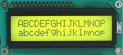
Liquid Crystal Display (LCD) is widely used in various electronics applications. It is commonly used in various systems to show different status and parameters. LCD16x2 has 2 lines with 16 characters in each line. Each character is made up of a 5x8 (column x row) pixel matrix.
To know basic working principle of LCD refer
http://www.j-display.com/english/technology/lcdbasic.html
LCD 16x2 Pin Description
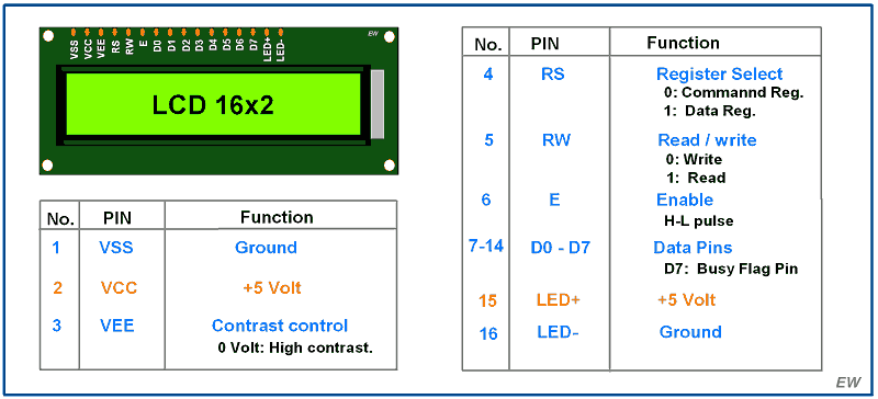
First two pins of LCD16x2 are used for ground and supply (+5 V).
Pin 3 - VEE pin
This pin is used for adjusting the contrast of the display. Voltage on this pin defines contrast on display, lower the voltage, higher the contrast. We can connect 4.7 k pot for contrast adjustment or simply connect this pin to ground to get maximum contrast.
Pin 4 –RS: Register Select pin
RS = 0: Data on the D0 to D7 pins is considered as a command.
RS = 1: Data on the D0 to D7 pins is considered as data to display on LCD16x2.
Pin 5 – RW: Read / Write pin
RW = 0: Write data to the LCD
RW = 1: Read data from the LCD
Pin 6 –E: Enable
This pin is used to latch the data present on the data pins D0 to D7. High to low pulse with a minimum width of 450 ns is required to latch the data to the display.
Pins 7:14 - DATA pins D0 to D7
Data pins are used to send data/command to the LCD16x2 as parallel 8 data bits.
Pin 15:16 - LED + and LED -
Liquid Crystal Displays don’t have their own light like seven segment displays. Therefore, the module has a backlight LED. Supply to this LED is provided through these pins.
Specification of LCD16x2
- Display Type: Alphanumeric character display
- Character Format: 5x8 dots matrix format
- Display Size: 16 characters x 2 lines
- Display Color: Blue or Green
- Backlight: LED backlight
- Voltage Supply: 5V DC
- Operating Temperature: -20°C to +70°C
- Interface: 4-bit or 8-bit mode
- Dimension: 84.0 x 44.0 x 13.0 mm
LCD 16x2 Commands
While interfacing an LCD16x2 with any microcontroller, firstly we need to initialize the LCD. For that, we need to send some commands. Similarly, to clear the display or for changing the position we need to send commands. So basically, we can say that LCD16x2 is controlled by using commands.
Commonly Used LCD16x2 Commands
| Code (HEX) | Command to LCD | Execution Time |
| 0x01 | Clear the display screen | 1.64ms |
| 0x06 | Shift the cursor right (e.g. data gets written in an incrementing order, left to right) | 40 us |
| 0x0C | Display on, cursor off | 40 us |
| 0x0E | Display on, cursor blinking | 40 us |
| 0x80 | Force the cursor to the beginning of the 1st line | 40 us |
| 0xC0 | Force the cursor to the beginning of the 2nd line | 40 us |
| 0x10 | Shift cursor position to the left | 40 us |
| 0x14 | Shift cursor position to the right | 40 us |
| 0x18 | Shift entire display to the left | 40 us |
| 0x1C | Shift entire display to the right | 40 us |
| 0x38 | 2 lines, 5x8 matrix, 8-bit mode | 40 us |
| 0x28 | 2 lines, 5x8 matrix,4-bit mode | 40 us |
| 0x30 | 1 line, 8-bit mode | 40us |
| 0x20 | 1 line, 4-bit mode | 40us |
Now, while printing a character on LCD16x2, we need to send the ASCII code of that character to LCD16x2. Suppose, we want to print a character ‘H’ on the LCD, then we should send 0x48 (ASCII code of ‘H’) data to the LCD16x2. The LCD16x2 has its own controller, which does the printing job on the LCD16x2.
LCD 16x2 4-bit Mode Configuration
Only four GPIO pins are connected to LCD data (D4-D7) pin which helps to save GPIO pins. By default, LCD16x2 is in 8-bit mode. To use LCD16x2 in 4-bit mode, we need to send some commands for LCD initialization and configuration. To send these commands following data formats should follow.
| D7 | D6 | D5 | D4 | D3 | D2 | D1 | D0 |
| 0 | 0 | 1 | DL | N | F | - | - |
DL: Interface Data length
0 =4-bit
1 = 8-bit
N: Number of display lines
0 = 1 line
1 = 2 line
F: Character Font
0 = 5x8 dots
1 = 5x10 dots
D1:D0: These bits are set to 0.
D7:D6: These bits are set to 0.
D5: This bit should set to 1.
Note: To configure LCD 16x2 in a 4-bit mode, we should send 2 at higher nibble (D4 - D7) to LCD 16x2. As only four (D4 - D7) data lines need to be connected to the microcontroller, we need to send 0x02 as a command, which will write 0 to higher nibble (D4-D7) and then again write 2 to higher nibble, which will set the LCD in 4-bit mode. Note that we can provide any command with lower nibble as 2 i.e. 0x32, 0x42 etc. except 0x22 to initialize display in 4-bit mode.
LCD 16x2 Custom Character
lets see how to display the custom character on LCD16x2 display.
LCD16x2 can display user defined custom characters. This can be used for displaying symbols and different patterns.
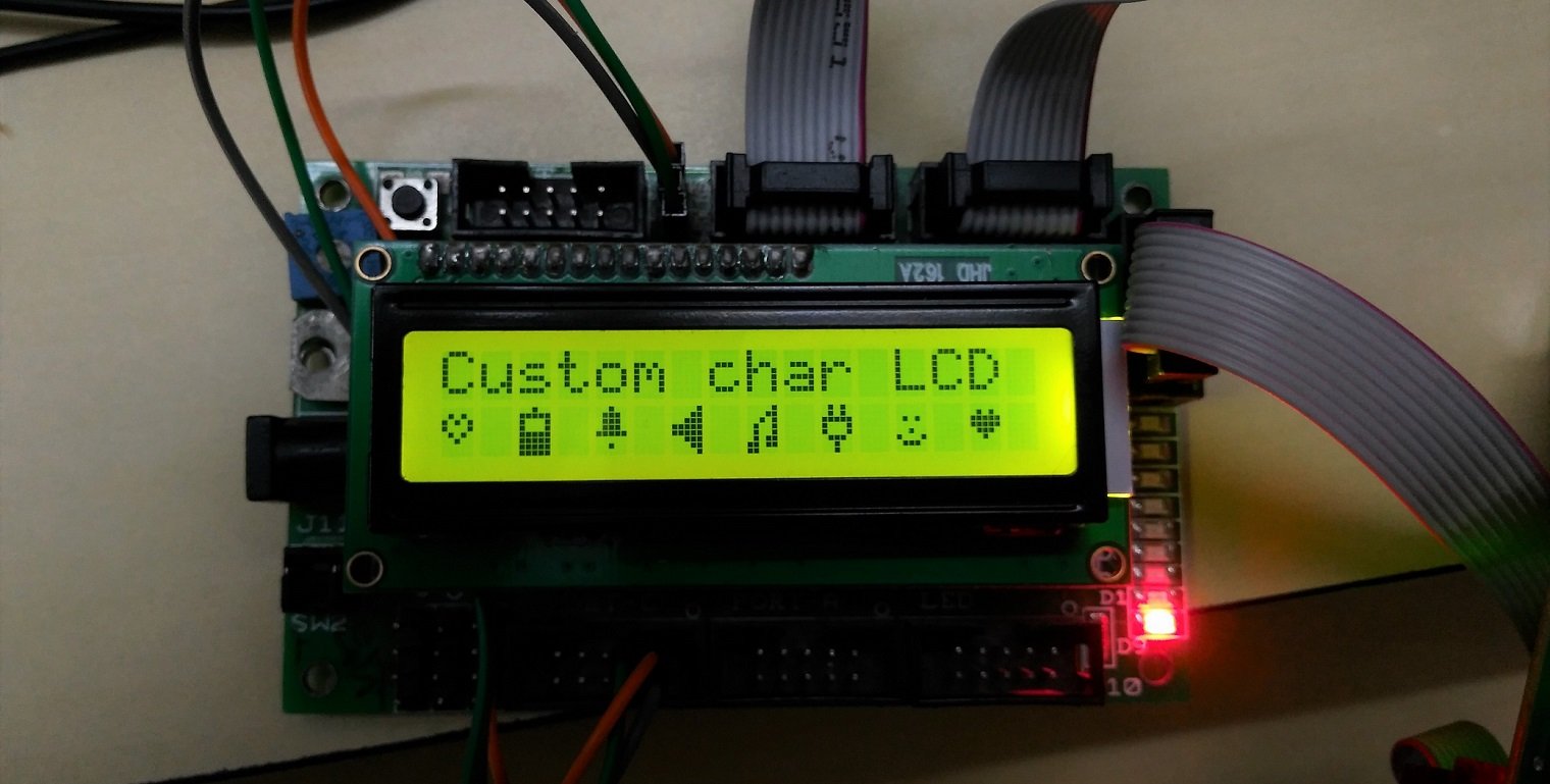
As we know, to print character symbol on LCD, we have to send ASCII code. LCD16x2 also has feature, where we can print our own custom character, which is not included in ASCII set of character.
E.g. J, ©, ∞ etc.
CGRAM
LCD16x2 has memory space of 64 bytes called as CGRAM (character generator RAM). It is used to make custom patterns. We just have to write custom pixel values in this memory space.
| Command | Code | Description | Execution Time | ||||
| RS | R/W | DB7 | DB6 | DB5-DB0 | |||
| Set CGRAM Address | 0 | 0 | 0 | 1 | Address | This is used to set the address of CGRAM. | 40us |
While providing the address of CGRAM, we have to keep DB6 line always high. This means that address starts from 0x40 to store custom character on CGRAM.
How to Build custom character for LCD16x2
On LCD16x2 one character is made up by 5x8 pixel matrix. Consider that we have to design Bell shape custom character. As in diagram, we have to define pixel values, 0 for pixel OFF and 1 for Pixel ON.
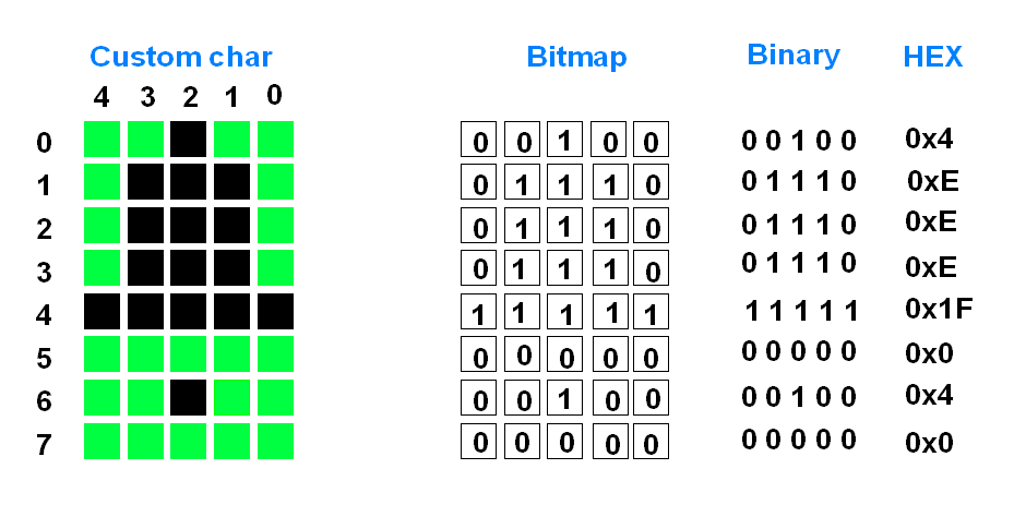
So, we get total eight values for one custom character.
For making custom characterLCD16x2, you can refer this link: https://omerk.github.io/lcdchargen/
Storing Custom Character
Custom Characters are stored at CGRAM’s memory location. CGRAM is 64 bytes.
Custom character address starts from 0x40 and ends at 0x7F.
So we can define total 8 custom characters.
| Character No. | CGRAM Address |
| 1 | 0x40 - 0x47 |
| 2 | 0x48 - 0x4F |
| 3 | 0x50 - 0x57 |
| 4 | 0x58 - 0x5F |
| 5 | 0x60 - 0x67 |
| 6 | 0x68 - 0x6F |
| 7 | 0x70 - 0x77 |
| 8 | 0x78 - 0x7F |
For more details about LCD, refer the LCD datasheet given in attachments section below.
Alternate options for LCD16x2
- LCD 20x4
- GLCD 128x64
- Nokia 5110 LCD
- OLED SSD1306 128x64
- OLED SSD1306 128x32
LCD16x2 Display interfacing with Arduino
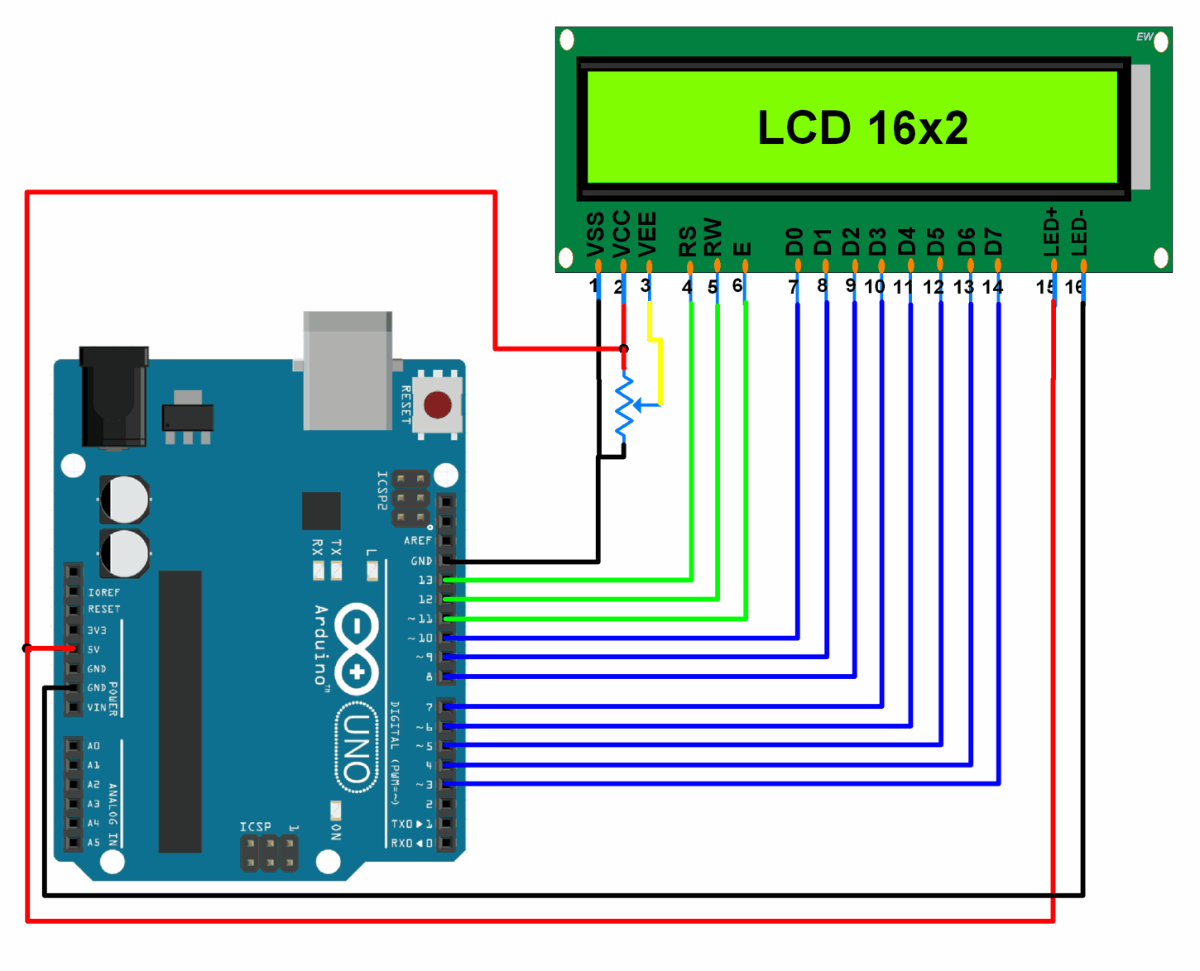
LCD16x2 Display Code for Arduino
#include<LiquidCrystal.h>
/* Create object named lcd of the class LiquidCrystal */
LiquidCrystal lcd(13, 12, 11, 10, 9, 8, 7, 6, 5, 4, 3);    /* For 8-bit mode */
//LiquidCrystal lcd(13, 12, 11, 6, 5, 4, 3);      /* For 4-bit mode */

unsigned char Character1[8] = { 0x04, 0x1F, 0x11, 0x11, 0x1F, 0x1F, 0x1F, 0x1F };     /* Custom Character 1 */
unsigned char Character2[8] = { 0x01, 0x03, 0x07, 0x1F, 0x1F, 0x07, 0x03, 0x01 };     /* Custom Character 2 */

voidsetup(){
  lcd.begin(16,2);                             /* Initialize 16x2 LCD */
 lcd.clear();                                 /* Clear the LCD */
 lcd.createChar(0, Character1);   /* Generate custom character */
 lcd.createChar(1, Character2);
}

voidloop(){
 lcd.setCursor(0,0);                    /* Set cursor to column 0 row 0 */
  lcd.print("Hello!!!!");                 /* Print data on display */
 lcd.setCursor(0,1);
 lcd.write(byte(0));                    /* Write a character to display */
  lcd.write(1);
}
The output of the code will be displaying "Hello!!!!" on the first row of a 16x2 LCD and two custom characters on the second row. The custom characters are generated and defined in the code using the createChar function and assigned to the characters with codes 0 and 1.
To know more about LCD 16x2 using Arduino refer to this link
Examples of LCD 16x2 interfacing
- LCD 16x2 with PIC18F4550 ( 8-bit mode, 4-bit mode, Custom character )
- LCD 16x2 with ATmega16 ( 8-bit mode, 4-bit mode, Custom character )
- LCD 16x2 with 8051 ( 8-bit mode, 4-bit mode, Custom character )
- LCD 16x2 with Arduino
- LCD 16x2 with TI Launchpad
- LCD 16x2 with LPC2148 (8-bit mode, 4-bit mode, Custom character)
Components Used |
||
|---|---|---|
| LCD16x2 Display LCD16x2 Display |
X 1 | |
| LCD 16x2 with I2C Interface LCD 16x2 with I2C Interface |
X 1 | |
Downloads |
||
|---|---|---|
|
|
LCD 16x2 Datasheet | Download |