Stepper Motor Basics
Stepper Motor is a brushless DC Motor. Control signals are applied to stepper motor to rotate it in steps.
Its speed of rotation depends upon rate at which control signals are applied. There are various stepper motors available with minimum required step angle.
Stepper motor is made up of mainly two parts, a stator and rotor. Stator is of coil winding and rotor is mostly permanent magnet or ferromagnetic material.
Working Principle of Stepper Motor
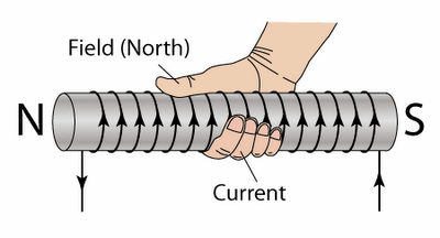
Current flowing through winding creates magnetic North and South pole on coil. If we wrap our right-hand fingers around coil in the direction of current flowing through the coil, then the thumb direction indicates the magnetic North Pole.
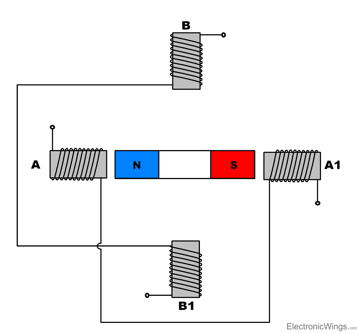
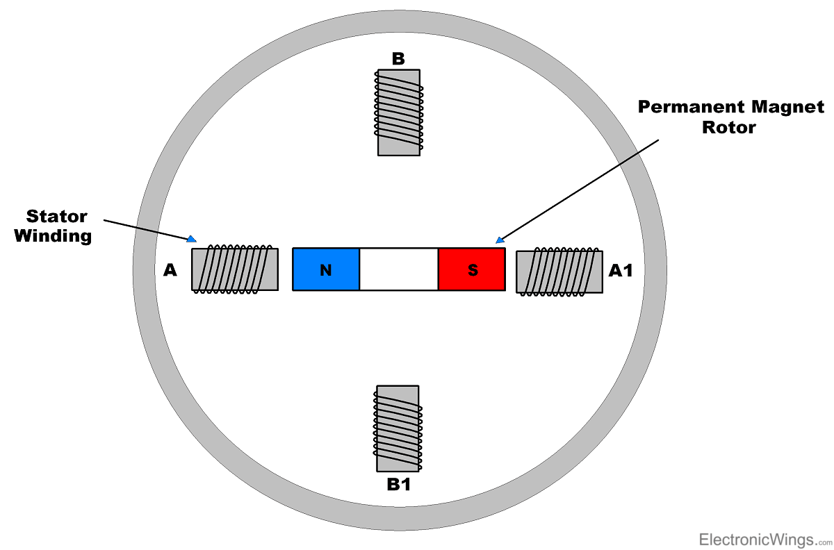
Stepper motor rotates in steps. To understand its principle, consider the logical diagram of its construction given below.
Two winding, A and B are the stator of motor. Permanent magnet having North and South poles is rotor of the motor.
The basic arrangement of stator and rotor in stepper motor is shown in figure below.
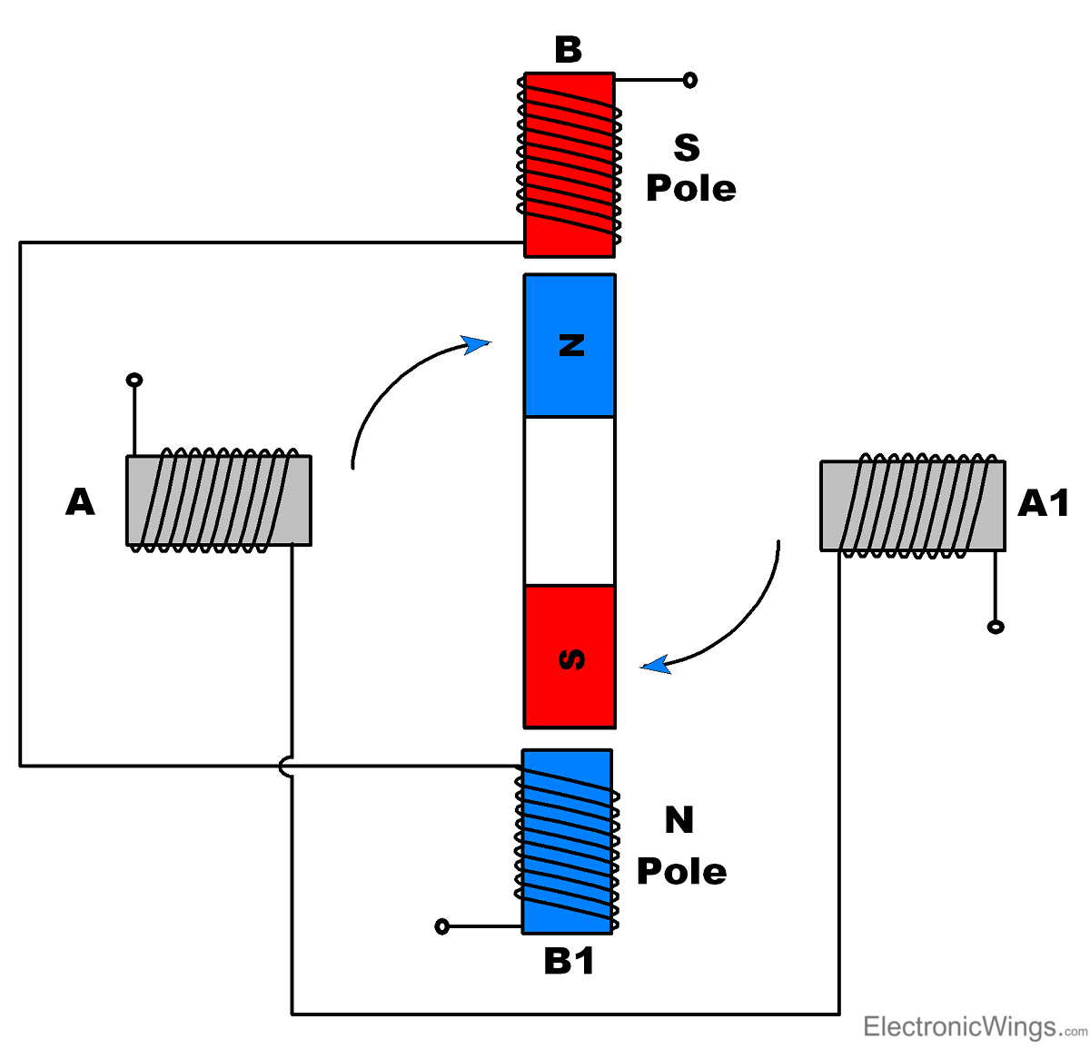
Now if we energise winding B, it will create North and South poles on winding B as shown in figure below which will attract opposite poles of magnet towards it. This causes rotor (permanent magnet) to rotate by a step.
Now, similarly for winding A, if we energise winding A, then the unlike poles will be attracted and make step as shown in figure below.
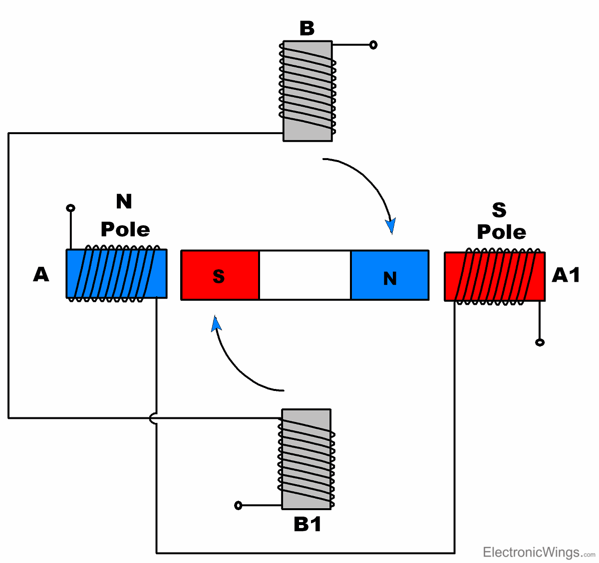
In this way, we can provide sequence of steps to create rotation.
Step Angle
Step angle is the minimum angle that stepper motor will cover within one move/step. Number of steps required to complete one rotation depends upon step angle. E.g. If step angle is of 45° then 8 steps are required to complete one rotation as shown in figure below.
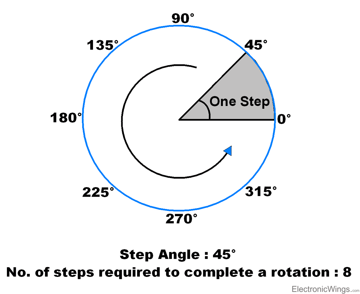
Depending upon stepper motor configuration, step angle varies e.g. 0.72°, 1.8°, 3.75°, 7.5°, 15° etc.
Stepper motors are classified depending upon construction and winding arrangement.
- Depending upon winding arrangement
- Unipolar Stepper Motor
- Bipolar Stepper Motor
- Depending upon construction
- Permanent Magnet Stepper Motor
- Variable Reluctance Stepper Motor
- Hybrid Stepper Motor
Let’s first see Unipolar Stepper Motor
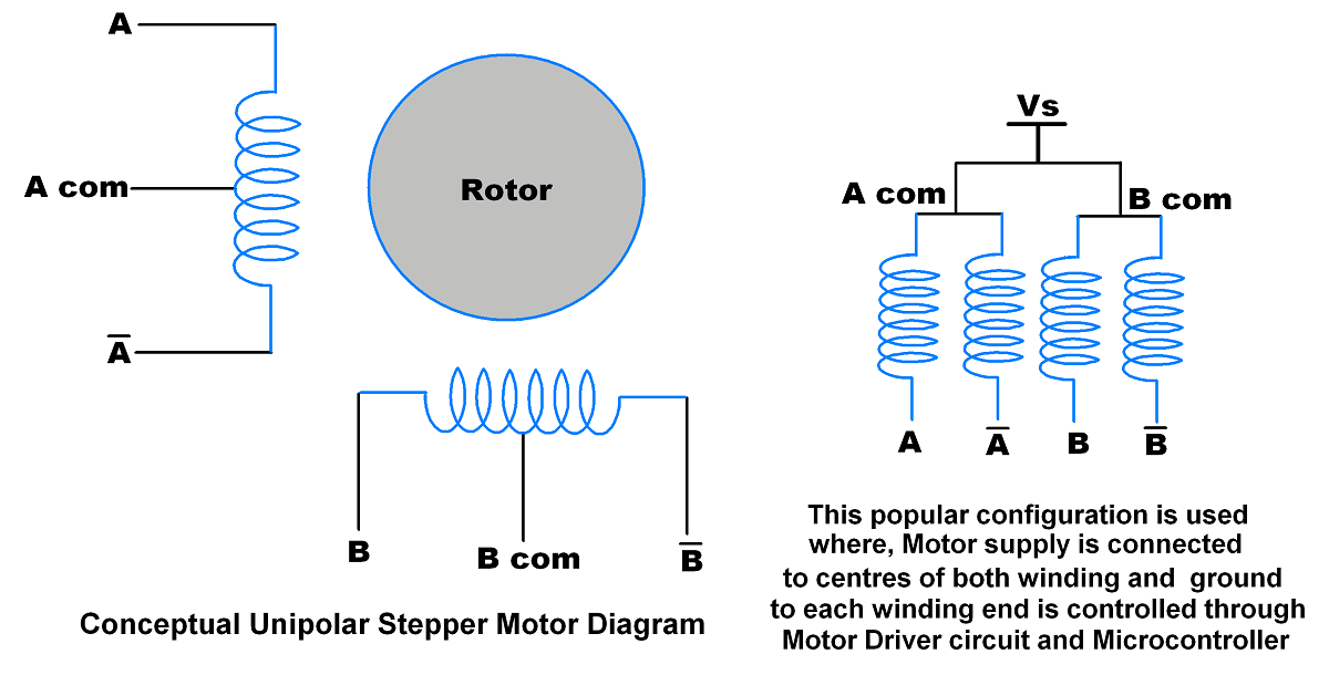
Unipolar Stepper Motor
- Unipolar Stepper Motor has centre tapped winding with 5 (If both centres are connected internally) or 6 wires as shown in below figure.
- Generally, these centre tapped connections are connected to the power supply.
- By providing ground path to the winding leads we can allow the flow of current through each half of coil which create magnetic poles. By altering poles sequentially, we can rotate rotor accordingly.
- The current is unidirectional in unipolar motor.
- Due to centre tap, each winding is divided i.e. current flows through half of winding.
- Due to its centre tap arrangement, we do not need to change current direction to change magnetic pole on winding. Here we just need to alter ground connection at winding ends.
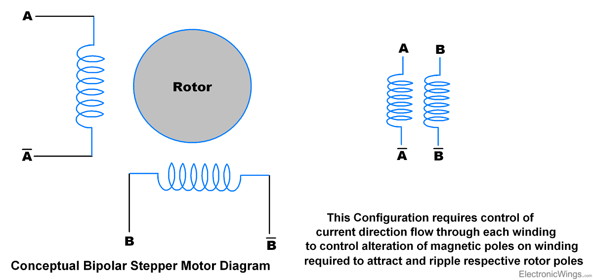
Bipolar Stepper Motor
- Bipolar stepper Motor has no centre tap connection. Normally it is of two windings i.e. 4 wire end as shown in below figure.
- Current flows through full winding of stator.
- The current is Bidirectional in Bipolar stepper motor i.e. we need to alter current direction through winding to alter magnetic pole of that winding.
Difference between Unipolar and Bipolar Stepper Motor
- As per name, they already differ in current direction.
- Also, due to unidirectional arrangement, Unipolar Stepper Motor do not require to control direction of current. So, it does not require H bridge like circuitry for bidirectional operation. A simple ULN2003 driver circuitry is used to drive it.
- Whereas in Bipolar Stepper Motor, it requires H bridge driver circuitry e.g. like L293D driver for bidirectional current control.
- Unipolar Stepper Motor has less torque than Bipolar Stepper Motor because in unipolar stepper motor current flows through half of the winding; whereas in bipolar stepper motor current flows through full winding.
Now let’s see how stepper motors are classified by construction
Stepper Motor Types
Permanent Magnet Stepper Motor
- Here, permanent magnet is used as rotor with electromagnetic stator winding.
- The rotor and stator of these Stepper Motor are not teethed.
- Supply is given to the stator, stator winding energized and produce magnetic north and south pole.
- This cause the rotor to rotate and to align with energized poles. Now by energizing next winding rotor will step towards it.
In this way, continuous sequence of winding pulses causes rotor to rotate continuous.
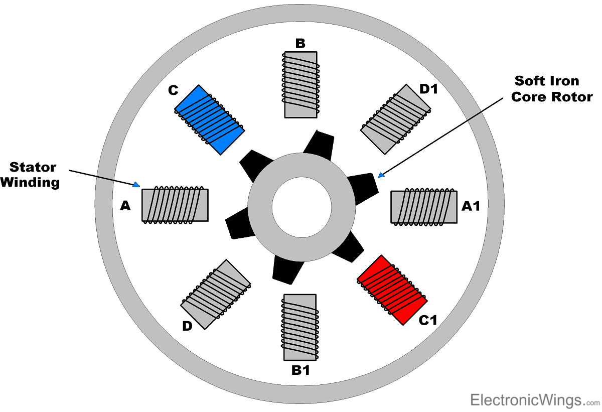
Variable Reluctance Stepper Motor
- Here Non-magnetic iron core is used as rotor.
- Stator is electromagnetic winding around rotor.
- Rotor consists of teeth. These teeth are attracted towards energized winding as magnetic path is generated around coil and rotor.
- Rotor experiences torque and aligns with energized coil to minimize the flux path.
- Now if next winding is energized then rotor will move towards it.
- In this way, continuous sequence of winding pulses cause rotor to rotate continuously.
- Note that rotor teeth are arranged in such manner, that at a time only one rotor teeth and energised winding coil pair will align while other teeth slightly deviate with other windings. As shown in figure below, energised winding C align with rotor teeth.
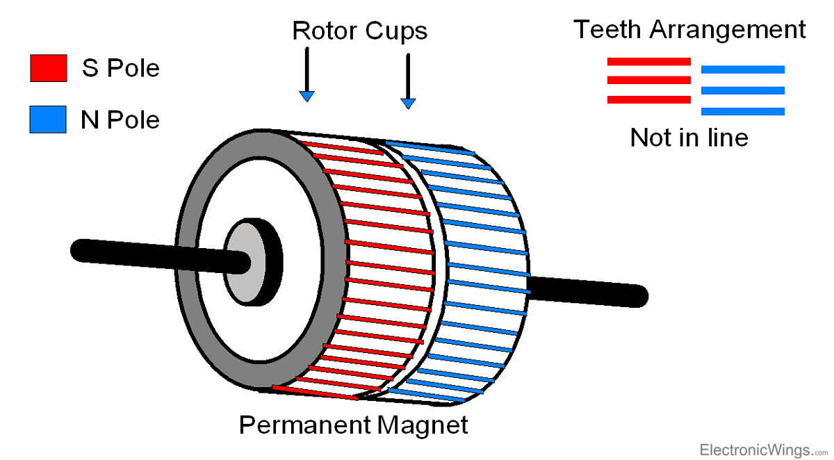
Hybrid Stepper Motor
- The Hybrid Motors are combination of permanent magnet and variable reluctance stepper motor.
- Permanent Magnet used inside the rotor and iron core outside of rotor. Permanent magnet forms the North and South poles on rotor.
- It has two rotor cups as shown in figure which consist of permanent magnet teeth.
- Note that their teeth are arranged in zigzag manner.
- Hybrid stepper motors have higher torque, and can achieve smaller step size.
How to Rotate Stepper Motor
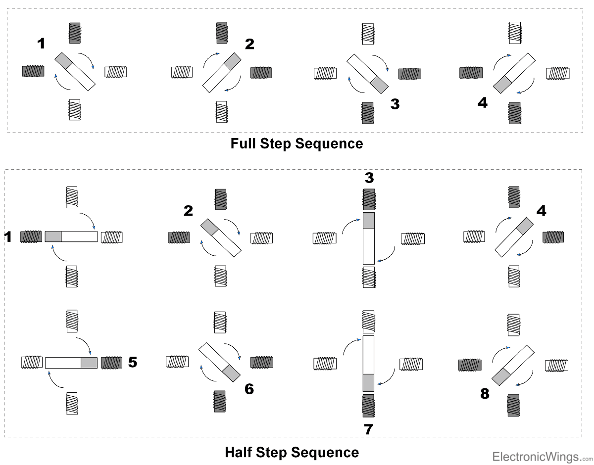
Stepper motor rotates in steps and for continuous or limited angle rotation we need to provide sequential steps. Mostly there are two step sequences used to rotate Stepper Motor as shown in below figure i.e.
- Full Step Sequence
Here motor moves through its basic step angle.
At a time two coils are excited.
- Half Step Sequence
Here motor moves half of its basic step angle.
Half step can be achieve by exciting both current and next coil.
Full step sequence
| Step | A | B | C | D |
| 1 | 1 | 0 | 0 | 1 |
| 2 | 1 | 1 | 0 | 0 |
| 3 | 0 | 1 | 1 | 0 |
| 4 | 0 | 0 | 1 | 1 |
Half step sequence
| Step | A | B | C | D |
| 1 | 1 | 0 | 0 | 1 |
| 2 | 1 | 0 | 0 | 0 |
| 3 | 1 | 1 | 0 | 0 |
| 4 | 0 | 1 | 0 | 0 |
| 5 | 0 | 1 | 1 | 0 |
| 6 | 0 | 0 | 1 | 0 |
| 7 | 0 | 0 | 1 | 1 |
| 8 | 0 | 0 | 0 | 1 |
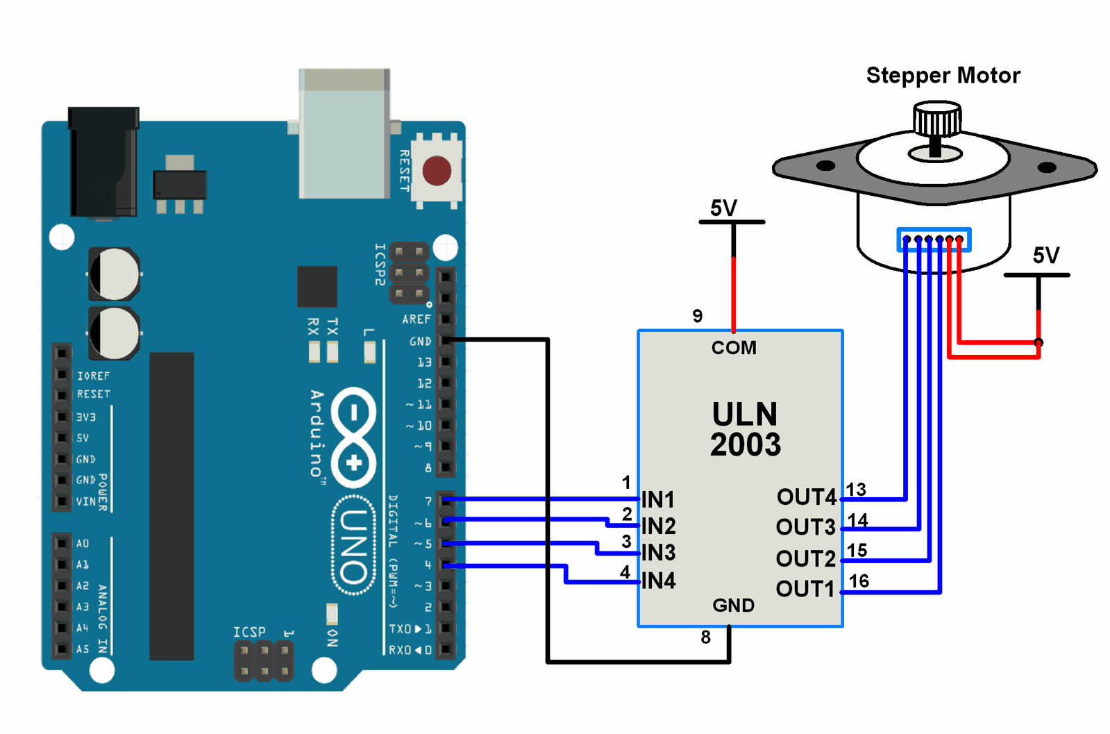
Connection Diagram of Stepper Motor with Arduino
Stepper Motor Code for Arduino
void setup() {
  pinMode(4, OUTPUT);
  pinMode(5, OUTPUT);
  pinMode(6, OUTPUT);
  pinMode(7, OUTPUT);
}

void loop() {
	/* Rotation in one direction */
  for(int i = 0; i<12; i++)
  {
    digitalWrite(7, HIGH);
    digitalWrite(6, LOW);
    digitalWrite(5, LOW);
    digitalWrite(4, LOW);
    delay(100);
    digitalWrite(7, HIGH);
    digitalWrite(6, HIGH);
    digitalWrite(5, LOW);
    digitalWrite(4, LOW);
    delay(100);
    digitalWrite(7, LOW);
    digitalWrite(6, HIGH);
    digitalWrite(5, LOW);
    digitalWrite(4, LOW);
    delay(100);
    digitalWrite(7, LOW);
    digitalWrite(6, HIGH);
    digitalWrite(5, HIGH);
    digitalWrite(4, LOW);
    delay(100);
    digitalWrite(7, LOW);
    digitalWrite(6, LOW);
    digitalWrite(5, HIGH);
    digitalWrite(4, LOW);
    delay(100);
    digitalWrite(7, LOW);
    digitalWrite(6, LOW);
    digitalWrite(5, HIGH);
    digitalWrite(4, HIGH);
    delay(100);
    digitalWrite(7, LOW);
    digitalWrite(6, LOW);
    digitalWrite(5, LOW);
    digitalWrite(4, HIGH);
    delay(100);
    digitalWrite(7, HIGH);
    digitalWrite(6, LOW);
    digitalWrite(5, LOW);
    digitalWrite(4, HIGH);
    delay(100);
  }
  digitalWrite(7, HIGH);
  digitalWrite(6, LOW);
  digitalWrite(5, LOW);
  digitalWrite(4, LOW);
  delay(100);

	/* Rotation in opposite direction */
  for(int j = 0; j<12; j++)
  {
    digitalWrite(7, LOW);
    digitalWrite(6, LOW);
    digitalWrite(5, LOW);
    digitalWrite(4, HIGH);
    delay(100);
    digitalWrite(7, LOW);
    digitalWrite(6, LOW);
    digitalWrite(5, HIGH);
    digitalWrite(4, HIGH);
    delay(100);

    digitalWrite(7, LOW);
    digitalWrite(6, LOW);
    digitalWrite(5, HIGH);
    digitalWrite(4, LOW);
    delay(100);
    digitalWrite(7, LOW);
    digitalWrite(6, HIGH);
    digitalWrite(5, HIGH);
    digitalWrite(4, LOW);
    delay(100);

    digitalWrite(7, LOW);
    digitalWrite(6, HIGH);
    digitalWrite(5, LOW);
    digitalWrite(4, LOW);
    delay(100);
    digitalWrite(7, HIGH);
    digitalWrite(6, HIGH);
    digitalWrite(5, LOW);
    digitalWrite(4, LOW);
    delay(100);

    digitalWrite(7, HIGH);
    digitalWrite(6, LOW);
    digitalWrite(5, LOW);
    digitalWrite(4, LOW);
    delay(100);
    digitalWrite(7, HIGH);
    digitalWrite(6, LOW);
    digitalWrite(5, LOW);
    digitalWrite(4, HIGH);
    delay(100);
  }
  digitalWrite(7, LOW);
  digitalWrite(6, LOW);
  digitalWrite(5, LOW);
  digitalWrite(4, HIGH);
  delay(100);
}
The above code is to run the stepper motor in a forward and reverse direction
To know more about stepper motor using Arduino refer to this link