Introduction
A magnetometer is used as a compass in Mobiles Phones, Navigation systems in vehicles to indicate directions.
A magnetometer is used for measurement of magnetic field direction in space. Most navigation systems use electronic compasses to determine heading direction. It has several types such as fluxgate, magnetoresistive, magneto-inductive and others.
Working Principle
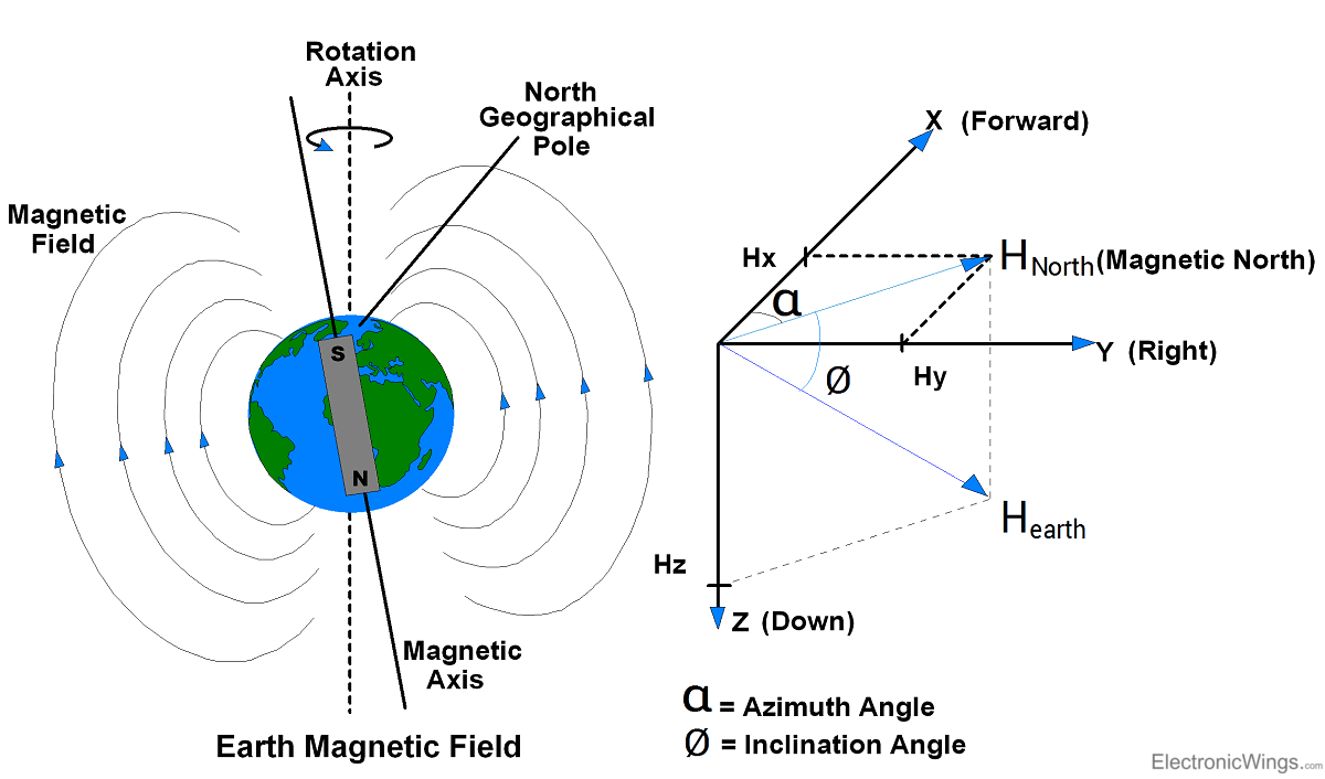
Earth’s magnetic field is present in space which points towards the magnetic north as shown in below image. Current carrying conductor also generates a magnetic field around itself. Hence, whenever a current carrying conductor is placed in space, it experiences the effect of the earth’s magnetic field affecting the flow of the electrons through that conductor. These changes in the flow of the electrons are used for identifying the heading or direction of the magnetic field. This is the basic working principle of the magnetometer.
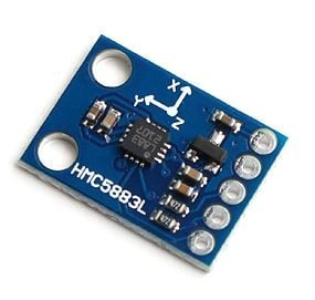
3-Axis Digital Compass IC HMC5883L
- HMC5883L uses magnetoresistive sensor arranged in a bridge circuit, which is made of nickel-iron (Ni-Fe magnetic film) material.
- Its electrical resistance varies with the change in the applied magnetic field.
- The correspondent movement of the nickel-iron material in space experiences earth’s magnetic field which changes the material’s resistance, and hence we get resultant voltage changes across the bridge. This change in voltages is used to get the magnetic field direction in space.
The components of Earth Magnetic Field (Hx, Hy) are parallel to the earth’s surface and are used in determining the compass direction. Only the X and Y components of the earth’s field are used in determining the azimuth angle, or the compass direction.
Azimuth (x=0, y<0) = 90
Azimuth (x=0, y>0) = 270
Azimuth (x<0) = 180 - [arc tan(y/x)] *180/π
Azimuth (x>0, y<0) = - [arc tan(y/x)] *180/π
Azimuth (x>0, y>0) = 360 - [arc tan(y/x)] *180/π
Which gives Azimuth angle (α) from 0 to 360 degree in X direction relative to the magnetic north.
With this, let’s see some of the features of HMC5883L like,
- It can be used for low-cost compassing and magnetometry.
- It has 12-bit ADC and compass heading accuracy is up to 1° to 2°.
- It has Honeywell’s Anisotropic Magneto Resistive (AMR) technology which provides precision in axis sensitivity and linearity.
- It uses I2C communication protocol to communicate with microcontrollers.
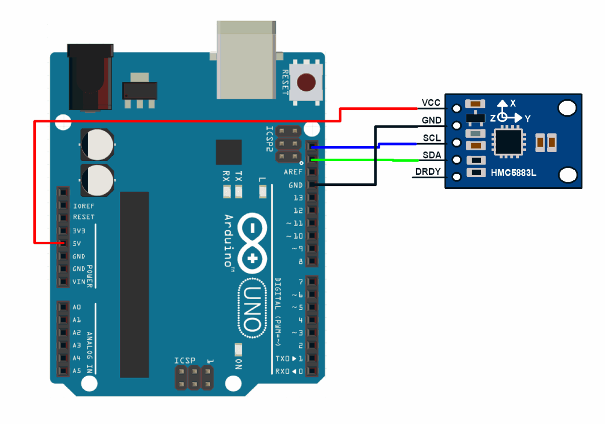
HMC5883l Pinout
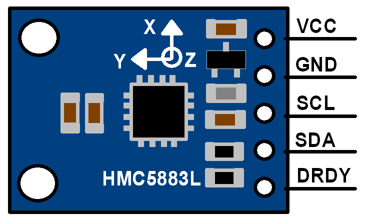
HMC5883L module has five pins as shown in above figure,
VCC: Connect 5V DC supply to this pin.
GND: Connect ground to this pin.
SCL: Connect serial clock out from master device to this pin.
SDA: Connect serial data line from master device to this pin.
DRDY: Data Ready status signal pin output from module to master device.
This device is controlled through on-chip registers, shown in the table below:
Specification of HMC5883L Magnetometer
- Supply Voltage: 2.16 to 3.6 V DC
- Communication: I2C (Inter-Integrated Circuit)
- Sensitivity: ±0.88 mG per digit
- Field Range: ±8.1 Gauss
- Data Output Rate: 0.75, 1.5, 3, 7.5, 15 Hz
- Operating Current: 130 μA
| Address Location | Name | Access |
|---|---|---|
| 00 | Configuration Register A | Read/Write |
| 01 | Configuration Register B | Read/Write |
| 02 | Mode Register | Read/Write |
| 03 | Data Output X MSB Register | Read |
| 04 | Data Output X LSB Register | Read |
| 05 | Data Output Z MSB Register | Read |
| 06 | Data Output Z LSB Register | Read |
| 07 | Data Output Y MSB Register | Read |
| 08 | Data Output Y LSB Register | Read |
| 09 | Status Register | Read |
| 10 | Identification Register A | Read |
| 11 | Identification Register B | Read |
| 12 | Identification Register C | Read |
From above table,
- Configuration Register A is used to set the data output rate and the measurements mode of the module.
- Configuration Register B is used to set the gain of the device.
- Mode register is used to set the operating mode of the HMC5883L like Idle mode, Single-measurement mode, Continuous measurement mode.
- Data Output Registers are used to store X, Y and Z axis values. As these values are 16-bit wide, those values are stored in two 8-bit registers. So, we need to read each axis value from two 8-bit registers. These values are in 2’s complement form i.e. we need to copy it in 16-bit signed variable to get decimal value.
- Status Register gives device ready status and status of data output register i.e. whether it is locked or not.
- Identification Registers are used to identify the device.
Declination Angle
As shown in above figure of earth’s magnetic field, the true north (earth’s rotation axis) and magnetic north are differing from each other. At different locations around the earth, magnetic north and true north can differ by up to ±25 degrees. This difference is called as Declination angle.
As our compass points to magnetic north, which is not a true north, to find a true heading angle, we need to add declination angle in the heading angle calculated from HMC5883l.
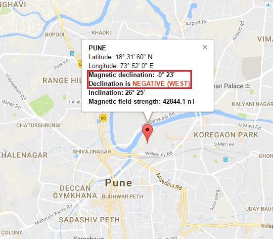
Find the declination angle for various geographic locations from the website: http://www.magnetic-declination.com
For example, if we are calculating heading direction from location Pune city, Maharashtra state, India then the declination angle is (-0° 23’).
Convert the angle from Degree Minute form into radiant form. For that, we can refer website (http://www.wolframalpha.com)
Therefore, the magnetic north heading for this location will be
-0° 23’ = 6.69mrad i.e. 0.00669rad.
So, True Heading = Magnetic North Heading + (-0.00669)
Communicate with HMC5883L
HMC5883L uses the I2C protocol for communication. HMC5883L act as a slave device. Its I2C device address is 0x1E. Its read and write operation addresses are:
Slave device write address (SLA+W): 0x3C
Slave device read address (SLA+R): 0x3D
Alternate options for HMC5883L
- LSM303D - Combination accelerometer and magnetometer with I2C interface
- QMC5883L - Low-cost magnetometer with an I2C interface
- BMM150 - Triaxial low power geomagnetic sensor with I2C/SPI interface
- AK8963 - 3-axis magnetic sensor with I2C/SPI interface
- STMicroelectronics LIS3MDL - Low power, high-performance 3-axis magnetometer with I2C interface
- AS5047D - Contactless high-resolution magnetic position sensor with SPI interface
HMC5883L Magnetometer interfacing with Arduino
HMC5883L Magnetometer Code for Arduino
Here, we will be using James Sleeman’s HMC5883L library from GitHub.
Download this library from here.
/*
 *
 * Compass.ino - Example sketch for reading a heading from an HMC5883L triple axis magnetometer.
 *
 * GY-273 Compass Module  -> Arduino
 * VCC -> VCC  (See Note Below)
 * GND -> GND
 * SCL -> A5/SCL, (Use Pin 21 on the Arduino Mega)
 * SDA -> A4/SDA, (Use Pin 20 on the Arduino Mega)
 * DRDY -> Not Connected (in this example)
 *
 * Voltage Note
 * ~~~~~~~~~~~~
 * The GY-273 Board has a 3v3 Regulator on it, and the SDA/SCL are pulled up to that so it is OK to
 * use with 5v Arduino's.
 *
 * If you are using any other breakout, or the raw IC, you need to be using 3v3 to supply and signal!
 *
 * Datasheet: http://goo.gl/w1criV
 *
 * Copyright (C) 2014 James Sleeman
 *
 * Permission is hereby granted, free of charge, to any person obtaining a
 * copy of this software and associated documentation files (the "Software"),
 * to deal in the Software without restriction, including without limitation
 * the rights to use, copy, modify, merge, publish, distribute, sublicense,
 * and/or sell copies of the Software, and to permit persons to whom the
 * Software is furnished to do so, subject to the following conditions:
 *
 * The above copyright notice and this permission notice shall be included in
 * all copies or substantial portions of the Software.
 *
 * THE SOFTWARE IS PROVIDED "AS IS", WITHOUT WARRANTY OF ANY KIND, EXPRESS OR
 * IMPLIED, INCLUDING BUT NOT LIMITED TO THE WARRANTIES OF MERCHANTABILITY,
 * FITNESS FOR A PARTICULAR PURPOSE AND NONINFRINGEMENT. IN NO EVENT SHALL THE
 * AUTHORS OR COPYRIGHT HOLDERS BE LIABLE FOR ANY CLAIM, DAMAGES OR OTHER
 * LIABILITY, WHETHER IN AN ACTION OF CONTRACT, TORT OR OTHERWISE, ARISING FROM,
 * OUT OF OR IN CONNECTION WITH THE SOFTWARE OR THE USE OR OTHER DEALINGS IN
 * THE SOFTWARE.
 *
 * @author James Sleeman, http://sparks.gogo.co.nz/
 * @license MIT License
 */
#include<Arduino.h>
#include<Wire.h>
#include<HMC5883L_Simple.h>

// Create a compass
HMC5883L_Simple Compass;

voidsetup()
{
 Serial.begin(9600);
 Wire.begin();

  // Magnetic Declination is the correction applied according to your present location
  // in order to get True North from Magnetic North, it varies from place to place.
  //
  // The declination for your area can be obtained from http://www.magnetic-declination.com/
  // Take the "Magnetic Declination" line that it gives you in the information,
  //
  // Examples:
  //   Christchurch, 23° 35' EAST
  //   Wellington , 22° 14' EAST
  //   Dunedin    , 25° 8'  EAST
  //   Auckland   , 19° 30' EAST
  //
 Compass.SetDeclination(-0, 23, 'W');

  // The device can operate in SINGLE (default) or CONTINUOUS mode
  //   SINGLE simply means that it takes a reading when you request one
  //   CONTINUOUS means that it is always taking readings
  // for most purposes, SINGLE is what you want.
 Compass.SetSamplingMode(COMPASS_SINGLE);

  // The scale can be adjusted to one of several levels, you can probably leave it at the default.
  // Essentially this controls how sensitive the device is.
  //   Options are 088, 130 (default), 190, 250, 400, 470, 560, 810
  // Specify the option as COMPASS_SCALE_xxx
  // Lower values are more sensitive, higher values are less sensitive.
  // The default is probably just fine, it works for me.  If it seems very noisy
  // (jumping around), incrase the scale to a higher one.
 Compass.SetScale(COMPASS_SCALE_130);

  // The compass has 3 axes, but two of them must be close to parallel to the earth's surface to read it,
  // (we do not compensate for tilt, that's a complicated thing) - just like a real compass has a floating
  // needle you can imagine the digital compass does too.
  //
  // To allow you to mount the compass in different ways you can specify the orientation:
  //   COMPASS_HORIZONTAL_X_NORTH (default), the compass is oriented horizontally, top-side up. when pointing North the X silkscreen arrow will point North
  //   COMPASS_HORIZONTAL_Y_NORTH, top-side up, Y is the needle,when pointing North the Y silkscreen arrow will point North
  //   COMPASS_VERTICAL_X_EAST,    vertically mounted (tall) looking at the top side, when facing North the X silkscreen arrow will point East
  //   COMPASS_VERTICAL_Y_WEST,    vertically mounted (wide) looking at the top side, when facing North the Y silkscreen arrow will point West
 Compass.SetOrientation(COMPASS_HORIZONTAL_X_NORTH);

}

// Our main program loop.
voidloop()
{
   float heading = Compass.GetHeadingDegrees();

  Serial.print("Heading: \t");
   Serial.println( heading );
   delay(1000);
}
The above code works well and you will get the output. to know more in detail please visit Arduino HMC5883L Interface.
The output of the code will be a continuously updating display of the compass heading in degrees on the serial monitor of the Arduino IDE.
To know more about HMC5883L Magnetometer Sensor using Arduino refer to this link
Other interfacing Examples of HMC5883L Magnetometer
- HMC5883L Magnetometer Module Interfacing with ATmega16
- HMC5883L Magnetometer Module Interfacing with PIC18F4550
- HMC5883L Magnetometer Module Interfacing with TI Launchpad
- HMC5883L Magnetometer Module Interfacing with LPC2148
- HMC5883L Magnetometer Module Interfacing with NodeMCU
- HMC5883L Magnetometer Module Interfacing with Raspberry Pi
- HMC5883L Magnetometer Module Interfacing with Arduino
Components Used |
||
|---|---|---|
| HMC5883L Magnetometer Module Magnetometer HMC5883L is developed by Honeywell. It gives the heading direction. |
X 1 | |