Introduction
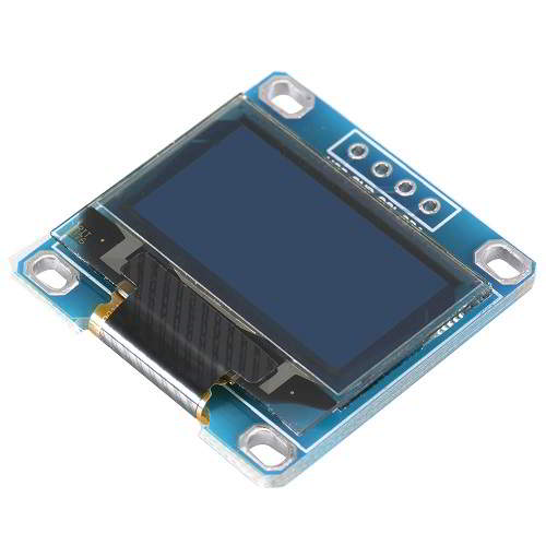
- OLED is Organic Light Emitting Diode that emits light in response to an electric current. OLED display works with no backlight so it can display deep black levels. It is small in size and light in weight than Liquid Crystal Displays.
- 128x64 OLED display is simple dot matrix graphic display. It has 128 columns and 64 rows which make it display of total 128x64 = 8192 pixels. By just turning on/off these pixel’s led we can display a graphical image of any shape on it.
OLED displays driven by SSD1306 driver IC. SSD1306 is a CMOS OLED driver with controller for OLED dot-matrix graphic display system. Due to use of SSD1306 driver, number of external components required and power consumption has reduced.
- OLED display is used for displaying text, images and various patterns. It is also suitable for mobile phone sub-display, MP3 player, calculators etc.
- OLED display has 256 steps for brightness control.
- OLED display also available with different resolution like 128x32, 128x64. OLED display in above image has resolution of 128x64 pixels.
Available Interfaces for OLED
OLED display module can be interfaced with microcontrollers using three interfaces given below:
6800/8000 series compatible Parallel Interface
In this interface 8-bit data send/receive could be done through parallel lines i.e. D0-D7.
I2C interface
In this interface, data send/receive could be done serially through SDA line.
Serial Peripheral Interface
In this interface, data send/receive could be done serially through SDI and SDO lines.
Note: The module illustrated here has I2C interface pins so all the discussion below is considering I2C as interfacing standard.
There are different types of OLED modules are available in market, having different resolutions, communication protocol (as discussed in above Available Interfaces for OLED section) and pixel colours (e.g. blue, yellow, white). Some modules support multi-colours as well.
Specification of ssd1306 128x64 OLED
- Display Type: OLED (Organic Light Emitting Diode)
- Display Size: 128x64 pixels
- Display Driver: ssd1306
- Display Colors: Monochrome (White), Yellow, and Blue
- Operating Voltage: 3.3V to 5V
- Interface: I2C
- Operating Current: ~20mA
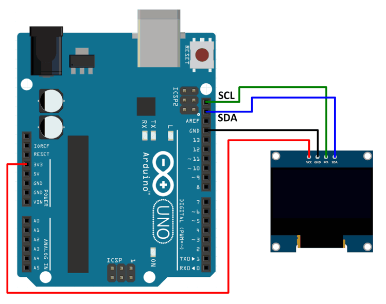
OLED Display Pins (I2C interface)
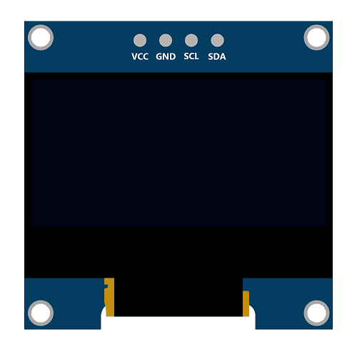
SDA (Serial Data):
SDA is used to transmit data between master and slave. The data and acknowledgment are sent through SDA.
SCL (Serial Clock):
It is a clock signal. This pin transmits clocks to slave, SCL. Data will be sent to other devices on clock tick event. Only master device has control over this SCL line
VCC:
This is power supply pin. +3.3V supply is required. More than 3.3 V supply can damage the display.
GND:
This is Ground pin. Connect ground of supply to this pin.
I2C Address of OLED display
In I2C interface devices are recognized by their slave address. OLED display has slave address format as shown in below image.
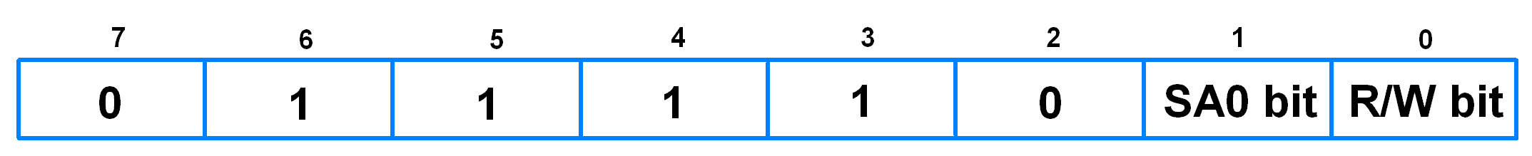
SA0(Slave Address) bit:
- This bit provides two slave address option to choose from.
R/W (Read/Write) bit:
- This bit is used to determine mode of operation i.e. I2C write or I2C read operation. 1 for read operation and 0 for write operation.
Now if SA0 bit is 0, then microcontroller can do read/write operation with OLED display using below I2C address.
- I2C write address is 0x78
- I2C read address is 0x79
Display Structure
OLED Display is mapped with GDDRAM of SSD1306.
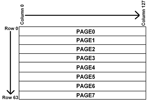
The GDDRAM (Graphics Display Data RAM) is a bit mapped static RAM. It holds the bit pattern to be displayed.
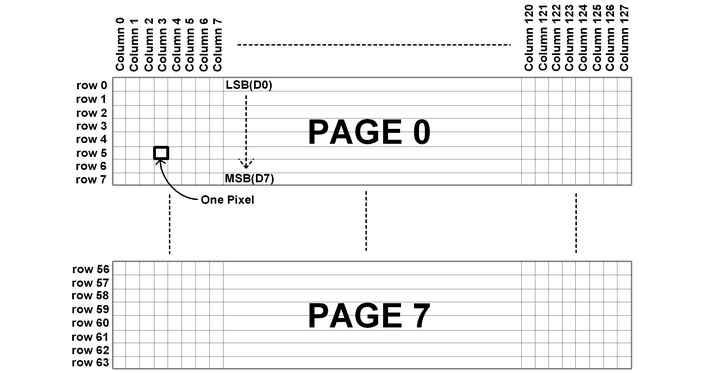
- The size of GDDRAM is 128 x 64 bits and it is divided into eight pages, from PAGE0 to PAGE7, which are used for monochrome 128x64 dot matrix display as shown in above figure.
- When a data byte (D0-D7) is written into GDDRAM, all the rows data pixels of the same page of the current column gets filled. Data bit D0 is written on the top row, while data bit D7 is written into bottom row as shown in Figure
Row and Column Mapping on OLED
- Display has total 8 pages, 64 rows and 128 Columns.
- Each page contains of 8 rows and 128 columns as shown in above figure.
- Display has total 128 columns called as segments.
- For displaying data at first location set page address to 0 and column address to 0. We should also select the end address of page and column.
- Maximum end address of page is 07H and Maximum column address is 7F H.
Commands for SSD1306
Note: Commands and initialization sequence given here is generalized and it worked for us.
Set Display Clock Divide Ratio/ Oscillator Frequency (0xD5 h):
- Bit 3 to 0: Display Clock Divide Ratio (D) Set the divide ratio to generate DCLK (Display Clock) from CLK. The divide ratio is from 1 to 16, with reset value = 1.
- Bit 7 to 4: Set oscillator frequency. The 4-bit value results in 16 different frequency settings. The default setting is 1000b.
Set Multiplex Ratio (0xA8 h):
- This command switches the default 63 multiplex mode to any multiplex ratio, ranging from 16 to 63.
Set Display Start Line (0x40 H~0x7F H):
- This command sets the Display Start Line register to determine starting address of display RAM, by selecting a value from 0 to 63. In our program we set this to zero and map RAM row 0 to COM 0.
Set Memory Addressing Mode (0x20 H):
There are three different addressing modes in SSD1306:
- Page addressing mode
- Horizontal addressing mode
- Vertical addressing mode
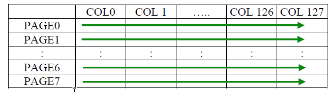
1. Page Addressing Mode:
- In page addressing mode, after the display RAM is read/written, the column address pointer is increased automatically by 1.
- If the column address pointer reaches column end address, the column address pointer is reset to column start address but page address pointer not points to next page.
- Hence, we need to set the new page and column addresses in order to access the next page RAM content.
- We need to set lower two bits to ‘1’ and ‘0’ for Page Addressing Mode.
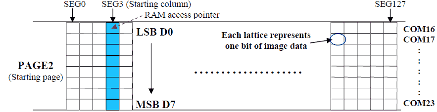
In page addressing mode, the following steps are required to define the starting RAM access pointer location:
- Set the page start address of the target display location by command B0h to B7h.
- Set the lower start column address of pointer by command 00h~0Fh.
- Set the upper start column address of pointer by command 10h~1Fh.
For example, if the page address is set to B2h, lower column address is 03h and upper column address is 10h, then that means the starting column is SEG3 of PAGE2. The RAM access pointer is located as shown in Figure. The input data byte will be written into RAM position of column 3.
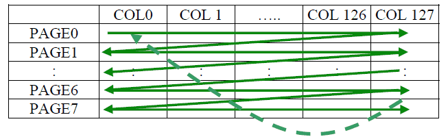
2. Horizontal Addressing Mode:
- In horizontal addressing mode, after the display RAM is read/written, the column address pointer is increased automatically by 1.
- If the column address pointer reaches column end address, the column address pointer is reset to column start address and page address pointer is increased by 1.
- When both column and page address pointers reach the end address, the pointers are reset to column start address and page start address
- We need to set last two digits to ‘0’ and ’0’ for horizontal addressing mode.
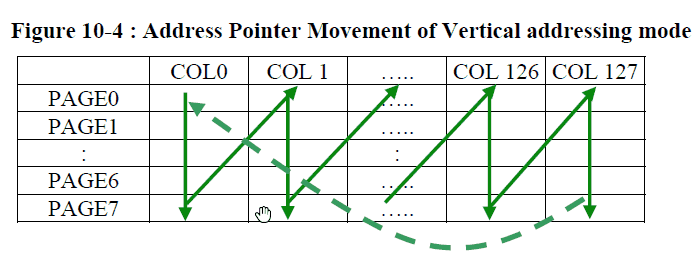
Vertical Addressing Mode:
- In vertical addressing mode, after the display RAM is read/written, the page address pointer is increased automatically by 1.
- If the page address pointer reaches the page end address, the page address pointer is reset to page start address and column address pointer is increased by 1.
- When both column and page address pointers reach the end address, the pointers are reset to column start address and page start address.
- We need to set last two digits to ‘0’ and ’1’ for vertical addressing mode.
In normal display data RAM read or write and horizontal/vertical addressing mode, the following steps are required to define the RAM access pointer location:
- Set the column start and end address of the target display location by command 21h.
- Set the page start and end address of the target display location by command 22h.
Set Column Address (0x21 H):
- This is a triple byte command. First byte specifies the command for setting column address (0x21 H).
- Second byte specifies the column start address and third byte specifies column end address.
- This command also sets the column address pointer to column start address.
Set Page Address (0x22 H):
- This is a triple byte command. First byte specifies the command for setting page address (0x22 H).
- Second byte specifies page start address and third byte is page end address.
- This command also sets the page address pointer to page start address.
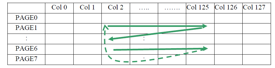
Example of column and row address pointer movement:
In the following example, Horizontal addressing mode is used. Column start address is set to 2 and column end address is set to 125.
- Page start address is set to 1 and end address is set to 6. In this case, the graphic display data RAM column accessible range is from column 2 to column 125 and from page 1 to page 6 only.
- In addition, the column address pointer is set to 2 and page address pointer is set to 1. After finishing read/write one pixel of data, the column address is increased automatically by 1 to access the next RAM location for next read/write operation.
- Whenever the column address pointer finishes accessing the end column 125, it gets reset back to the column 2 and page address is automatically increased by 1.
- While the end page 6 and end column 125 RAM location is accessed, the page address gets reset back to 1 and the column address is reset back to 2.
Set Contrast Control (0x81 H):
- This command sets the Contrast Setting of the display. The chip has 256 contrast steps from 00h to FF H. The segment output current increases as the contrast step value increases.
Set Pre-charge period (0xD9 H):
- This command is used to set the duration of the pre-charge period. The interval is counted in number of DCLK, where RESET equals 2 DCLKs.
Set VCOMH Deselect Level (0xDB H):
- This command adjusts the VCOMH regulator output.
Entire display on (0xA4 H/0xA5 H):
- A4 h command resumes the display from entire display “ON” stage.
- A5 h command forces the entire display to be “ON”, regardless of the contents of the display data RAM.
Set Normal/Inverse Display (0xA6h/0xA7h):
- A6 h command is for normal display.
- A7 h command is for inverse display.
Set Display ON/OFF (0xAE H/0xAF H):
- AE h: Set display OFF.
- AF h: Set display ON
Note: Clear the OLED display as it can print garbage value if left uncleared.
Warning:
- The data bit, which is transmitted during each SCL pulse, must keep at a stable state within the “HIGH” period of the clock pulse.
- Except in start or stop conditions, the data line can be switched only when the SCL is LOW.
- Both the data line (SDA) and the clock line (SCL) should be pulled up by external resistors.
Alternate options for 128x64 OLED
- OLED 128x32
- GLCD 128x64
- LCD16x2
- Nokia 5110 display
128x64 OLED Display interfacing with Arduino
Here, we are used Adafruit’s library for SSD1306. This library is available on GitHub.
Download this library from here.
This library is for monochrome displays only.
We will need the Adafruit GFX library as well for the patterns, images, and text that we will be displaying on the display.
Download this library from here.
Extract these libraries and add them to the libraries folder path of Arduino IDE.
For information about how to add a custom library to the Arduino IDE and use examples from it, refer Adding Library To Arduino IDE in the Basics section.
128x64 OLED Display Code for Arduino
#include<SPI.h>
#include<Wire.h>
#include<Adafruit_GFX.h>
#include<Adafruit_SSD1306.h>
#include"images_oled.h"

#define OLED_RESET 4
Adafruit_SSD1306 display(OLED_RESET); /* Object of class Adafruit_SSD1306 */

#if (SSD1306_LCDHEIGHT != 64)
#error("Height incorrect, please fix Adafruit_SSD1306.h!");
#endif

voidsetup(){
 display.begin(SSD1306_SWITCHCAPVCC, 0x3C); /* Initialize display with address 0x3C */
  display.clearDisplay(); /* Clear display */
 display.setCursor(15,5); /* Set x,y coordinates */
 display.setTextSize(1); /* Select font size of text. Increases with size of argument. */
 display.setTextColor(WHITE); /* Color of text*/
  display.println("ElectronicWings"); /* Text to be displayed */
 display.display();
  delay(500);
  /* Draw rectangle with round edges. Parameters (x_co-ord,y-co-ord,width,height,color) */
 display.drawRoundRect(5, 35, 35, 25, 1, WHITE);
  /* Draw circle. Parameters (x_co-ord of origin,y-co-ord of origin,radius,color) */
 display.drawCircle(65, 50, 12, WHITE);
  /* Draw triangle. Parameters (x0,y0,x1,y1,x2,y2,width,color). (x0,y0), (x1,y1) and (x2,y2) are the co-ord of vertices of the triangle  */
  display.drawTriangle(90, 60, 105, 35, 120, 60, WHITE);
 display.display();
  delay(1000);
 display.clearDisplay();
  /* Draw image. Parameters (x_co-ord, y_co-ord, name of array containing image, width of image in pixels, height in pixels, color) */
 display.drawBitmap(0, 0, Arduino_Logo, 128, 64, WHITE);
 display.display();
  delay(1000);
}

voidloop(){
 display.clearDisplay();
  display.drawBitmap(0, 0, Smiley_1, 128, 64, WHITE);
 display.display();
  delay(200);
 display.clearDisplay();
 display.drawBitmap(0, 0, Smiley_2, 128, 64, WHITE);
 display.display();
  delay(200);
 display.clearDisplay();
  display.drawBitmap(0, 0, Smiley_3, 128, 64, WHITE);
 display.display();
  delay(200);
 display.clearDisplay();
 display.drawBitmap(0, 0, Smiley_4, 128, 64, WHITE);
 display.display();
  delay(200);
}
The above code shows the smiley images on the OLED display
OLED Graphic Display Interfacing With Arduino UNO
Examples of OLED Display Interfacing
Components Used |
||
|---|---|---|
| SSD1306 OLED display OLED (Organic Graphic Display) display modules are compact and have high contrast pixels which make this display easily readable. They do not require backlight since the display creates its own light. Hence they consume less power. It is widely used in Smartphones, Digital display. |
X 1 | |
Downloads |
||
|---|---|---|
|
|
SSD1306 OLED Display Datasheet | Download |