What Is Accelerometer
An accelerometer is an electromechanical device that will measure acceleration force. It shows acceleration, only due to cause of gravity i.e. g force. It measures acceleration in g unit.
On the earth, 1g means acceleration of 9.8 m/s2 is present. On moon, it is 1/6th of earth and on mars it is 1/3rd of earth.
Accelerometer can be used for tilt-sensing applications as well as dynamic acceleration resulting from motion, shock, or vibration.
Specification of ADXL335
- Supply Voltage: 2.8V to 3.6V
- Current Consumption: 320uA
- Sensitivity: 300mV/g
- Bandwidth: 3Hz to 5kHz
- Dynamic Range: ±3g
- Operating Temperature: -40°C to +85°C
- Package Type: Surface Mount Plastic Package (LFCSP)
- Pin Configuration: 5 Pin, 1.27mm Pitch
- Output Type: Voltage Output
- Interface: SPI/I2C
- Output Range: 0V to Vcc
- Storage Temperature: -65°C to +150°C
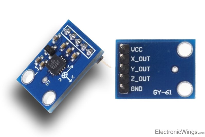
ADXL335 module
- The ADXL335 gives complete 3-axis acceleration measurement.
- This module measures acceleration within range ±3 g in the x, y and z axis.
- The output signals of this module are analog voltages that are proportional to the acceleration.
- It contains a polysilicon surface-micro machined sensor and signal conditioning circuitry.
How Accelerometer Works
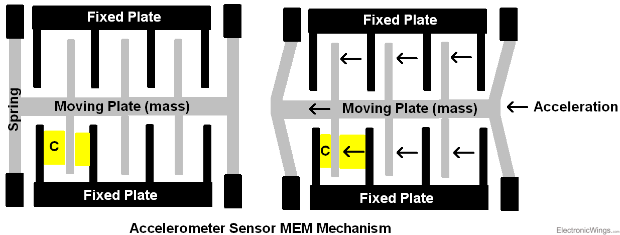
- As we can see from the above figure, basic structure of accelerometer consists fixed plates and moving plates (mass).
- Acceleration deflects the moving mass and unbalances the differential capacitor which results in a sensor output voltage amplitude which is proportional to the acceleration.
- Phase-sensitive demodulation techniques are then used to determine the magnitude and direction of the acceleration.
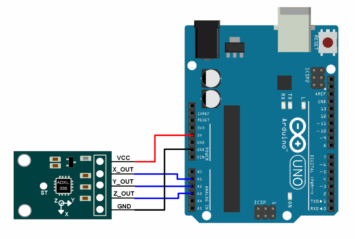
ADXL335 Accelerometer Module Pinout
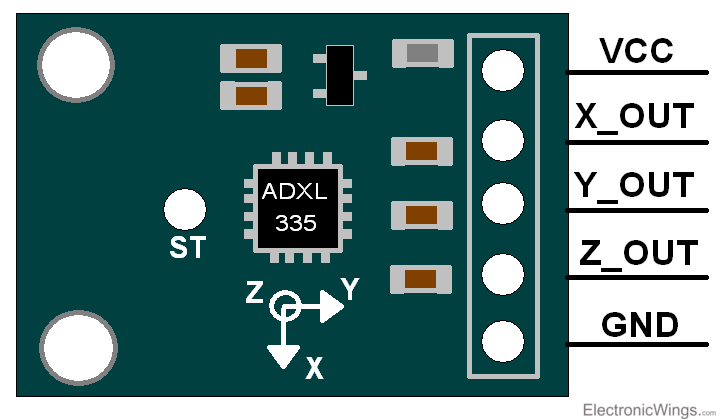
ADXL335 Accelerometer Module Pin Description
VCC: Power supply pin i.e. connect 5V here.
X_OUT: X axis analog output.
Y_OUT: Y axis analog output.
Z_OUT: Z axis analog output.
GND: Ground pin i.e. connect ground here.
ADXL335 accelerometer provides analog voltage at the output X, Y, Z pins; which is proportional to the acceleration in respective directions i.e. X, Y, Z.
Angles using ADXL335
We can calculate the angle of inclination or tilt by using X, Y, and Z values. Also, we can calculate Roll, Pitch, and Yaw angles with respect to X, Y, and Z axis. So first we need to convert 10-bit ADC values into g unit.
As per ADXL335 datasheet maximum voltage level at 0g is 1.65V and sensitivity scale factor of 330mV/g.
Above formula gives us acceleration values in g unit for X, Y, and Z axis as,
Axout = (((X axis ADC value * Vref) / 1024) – 1.65) / 0.330
Ayout = (((Y axis ADC value * Vref) / 1024) – 1.65) / 0.330
Azout = (((Z axis ADC value * Vref) / 1024) – 1.65) / 0.330
Note that, practically we get slightly different voltage at 0g. So, put the practical value of the voltage at 0g.
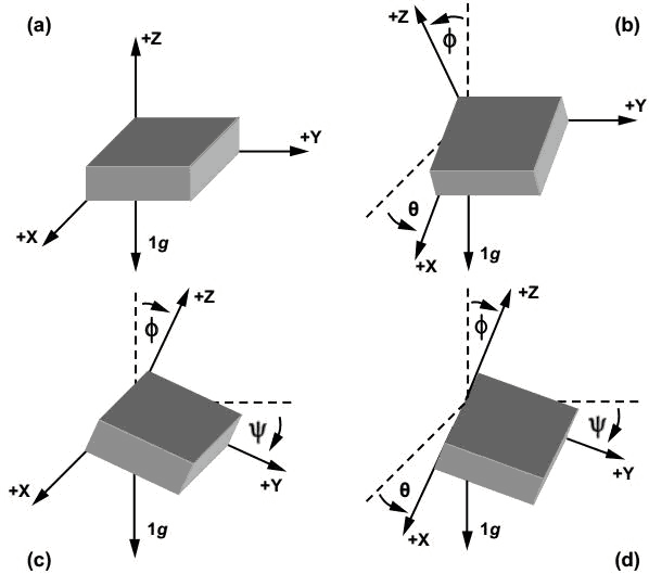
Angle of Inclination
- Angle of inclination means how much angle the device is tilted from its plane of surface.
- Angle of inclination are shown below figure.
- To calculate angle of inclination of X, Y, and Z axis from its reference, we need to use the below formulas.
Angle of inclination can be calculated as,
We get these angles in radians. So, multiply these values by (180/π) to get angle in degrees within range of -90° to +90° each axis.
Angle of Rotation
Now let’s find a complete angle of rotation (0° to 360°) around X, Y, Z axis, which we can also call as,
- Roll - Angle of rotation along the X axis
- Pitch - Angle of rotation along the Y axis
- Yaw - Angle of rotation along the Z axis
All of them are shown in below conceptual diagram.
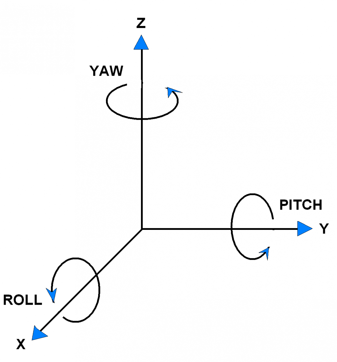
These angles are in degrees and can give readings of a complete rotation.
Now let’s calculate these angles. As we get Θ, Ψ and Φ in the range of -90° to +90°. Here we need to make these values in the range of -180° to +180° so that we can calculate a complete 360° angle of rotation. Let's calculate these with the arc tangent function which can be expressed as
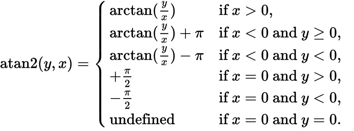
This function will produce the result in the range of -π to π. These values in radians we can convert into degree by multiplying it with (180/π ≈ 57.29577951) factor. So here we get values in -180° to +180°, and we can convert it to complete 0° to 360° by just adding 180° to range.
Hence, we get roll, pitch and yaw angles as,
Roll = (atan2(Ayout, Azout)) *57.29577951+180
Pitch = (atan2(Azout, Axout)) *57.29577951+180
Yaw = (atan2(Axout, Ayout)) *57.29577951+180
Note that, rotation along X (roll) and Y (pitch) axis will produce change in acceleration but rotation along with Z axis (yaw) will not produce any change in acceleration as it is perpendicular to the plane of surface. Hence using only accelerometer, yaw cannot be calculated.
We can also see this effect on X and Y axis when these axes are made perpendicular with plane of surface.
Alternate options for ADXL335
- ADXL345: This is a newer version of the ADXL335 and has more advanced features such as a higher range, better resolution, and an on-board FIFO buffer.
- LIS3DH: This is a low power accelerometer that is commonly used in wearable devices. It has a range of ±2g to ±16g and a high-resolution mode.
- MMA8452Q: This is a high-performance accelerometer that is commonly used in mobile devices. It has a range of ±2g to ±8g and can operate at up to 800 Hz.
- MPU-6050: This is an integrated accelerometer and gyroscope module. It is commonly used in motion control and stability applications and has a range of ±2g to ±16g.
- BMA220: This is a low-power accelerometer that is commonly used in wearable devices. It has a range of ±2g to ±4g and a high-resolution mode.
Difference between ADXL335 vs ADXL345
| Feature | ADXL335 | ADXL345 |
| Range | 3g | ±2g to ±16g |
| Resolution | 10-bit | 13-bit |
| Power Consumption | 330μA | 40μA to 350μA |
| Sampling Rate | 50Hz | 3.2kHz |
| Output Interface | Analog | I2C |
| Output Data Rate | 100Hz | 800Hz |
ADXL335 Accelerometer interfacing with Arduino
ADXL335 Accelerometer Code for Arduino
#include<math.h>
const int x_out = A1; /* connect x_out of module to A1 of UNO board */
const int y_out = A2; /* connect y_out of module to A2 of UNO board */
const int z_out = A3; /* connect z_out of module to A3 of UNO board */

voidsetup(){
 Serial.begin(9600);
}

voidloop(){
  int x_adc_value, y_adc_value, z_adc_value;
  double x_g_value, y_g_value, z_g_value;
  double roll, pitch, yaw;
  x_adc_value = analogRead(x_out); /* Digital value of voltage on x_out pin */
  y_adc_value = analogRead(y_out); /* Digital value of voltage on y_out pin */
  z_adc_value = analogRead(z_out); /* Digital value of voltage on z_out pin */
 Serial.print("x = ");
 Serial.print(x_adc_value);
 Serial.print("\t\t");
 Serial.print("y = ");
 Serial.print(y_adc_value);
 Serial.print("\t\t");
 Serial.print("z = ");
 Serial.print(z_adc_value);
 Serial.print("\t\t");
  //delay(100);

  x_g_value = ( ( ( (double)(x_adc_value * 5)/1024) - 1.65 ) / 0.330 ); /* Acceleration in x-direction in g units */
  y_g_value = ( ( ( (double)(y_adc_value * 5)/1024) - 1.65 ) / 0.330 ); /* Acceleration in y-direction in g units */
  z_g_value = ( ( ( (double)(z_adc_value * 5)/1024) - 1.80 ) / 0.330 ); /* Acceleration in z-direction in g units */

  roll = ( ( (atan2(y_g_value,z_g_value) * 180) / 3.14 ) + 180 ); /* Formula for roll */
  pitch = ( ( (atan2(z_g_value,x_g_value) * 180) / 3.14 ) + 180 ); /* Formula for pitch */
  //yaw = ( ( (atan2(x_g_value,y_g_value) * 180) / 3.14 ) + 180 ); /* Formula for yaw */
  /* Not possible to measure yaw using accelerometer. Gyroscope must be used if yaw is also required */

 Serial.print("Roll = ");
 Serial.print(roll);
 Serial.print("\t");
  Serial.print("Pitch = ");
 Serial.print(pitch);
 Serial.print("\n\n");
  delay(1000);
}
The output of the code is the digital values read from the x, y, and z outputs of the accelerometer module, as well as the calculated roll and pitch angles. The roll and pitch angles are printed to the serial monitor in degrees. The code also includes comments explaining the purpose and function of each part of the code.
To know more about ADXL335 Accelerometer Sensor using Arduino refer to this link
Examples of ADXL335 Accelerometer Module interfacing
- ADXL335 Accelerometer Module Interfacing with ATmega16
- ADXL335 Accelerometer Module Interfacing with PIC18F4550
- ADXL335 Accelerometer Module Interfacing with Arduino
- ADXL335 Accelerometer Module Interfacing with TI Launchpad
- ADXL335 Accelerometer Module Interfacing with LPC2148
- ADXL335 Accelerometer Module Interfacing with ESP32
Components Used |
||
|---|---|---|
| ADXL335 Accelerometer Module Accelerometer ADXL335 sensor measures acceleration of gravity. It is used to measure the angle of tilt or inclination in application systems such as in mobile devices, gaming applications, laptops, digital cameras, aeroplanes etc. |
X 1 | |