Introduction
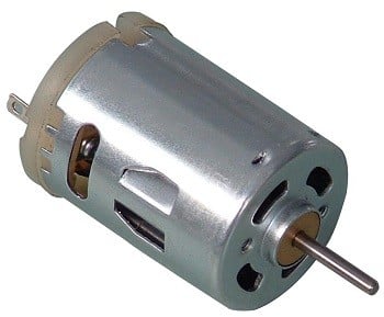
- DC motor uses Direct Current (electrical energy) to produce mechanical movement i.e. rotational movement. When it converts electrical energy into mechanical energy then it is called as DC motor and when it converts mechanical energy into electrical energy then it is called as DC generator.
- The working principle of DC motor is based on the fact that when a current carrying conductor is placed in a magnetic field, it experiences a mechanical force and starts rotating. Its direction of rotation depends upon Fleming’s Left Hand Rule.
- DC motors are used in many applications like robot for movement control, toys, quadcopters, CD/DVD disk drive in PCs/Laptops etc.
DC Motor Construction
It has mainly two major parts as,
- Stator – Static part of the motor.
- Rotor – Rotating part of the motor.
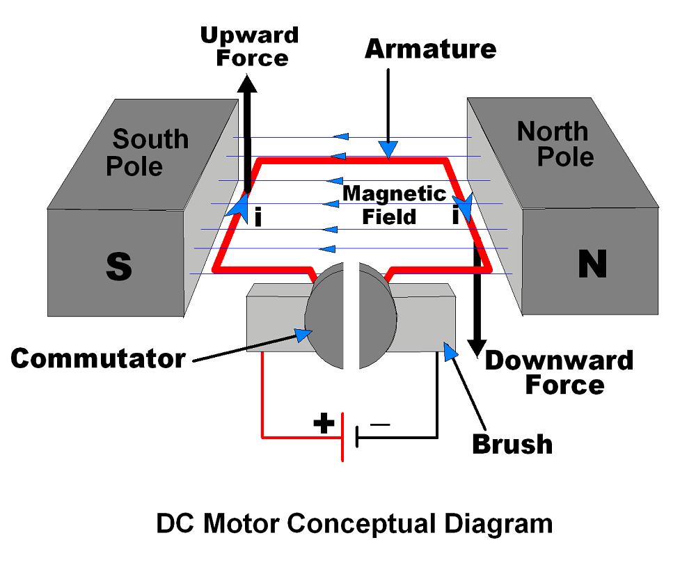
- The South and North poles of permanent magnet or Electromagnet are the stator part of the DC motor and armature connected with commutator is rotating part of the DC motor.
- South and North poles are used to create a magnetic field as shown in figure.
- The Armature is a conducting material which is placed in between magnetic field produced by North & South pole.
- The current (i) shown in figure is flowing through Armature.
- Brushes are used to attach DC supply to the Armature via commutator.
- Commutators have segments which are attached with each end of conducting Armature. Hence, commutator also rotates with Armature. Brushes are stator part which always keep in contact with commutator.
How DC Motor Works
As shown in above figure left hand side of armature lifting upward and right hand side of armature going downward. This is because of force, which depends upon direction of magnetic field and direction of current flowing through armature. Fleming’s Left Hand Rule is used to determine direction of force (upward/downward).
Let’s see how force act on armature conductor.
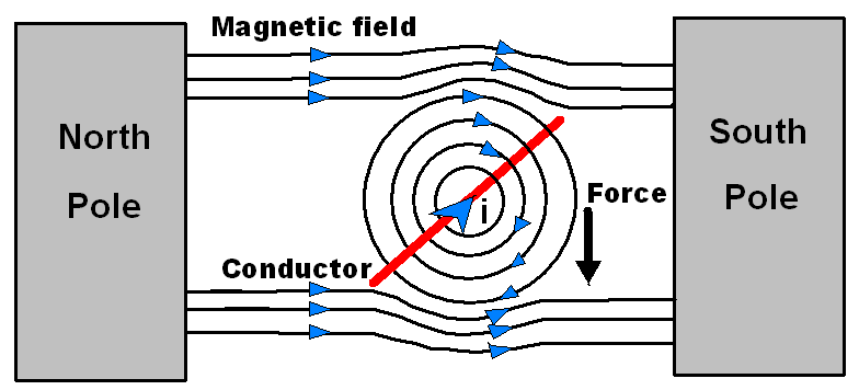
- As shown in above figure, the current (i) direction flowing through conductor is inward, hence magnetic field generated around conductor is having direction as per Right Hand Grip Rule shown in figure.
- The magnetic field in between North and South poles having direction from North to South as shown in figure.
- Magnetic lines of forces generated by current carrying conductor and by two poles are shown in figure. These both force lines look in same direction in the above half part of conductor whereas in the below half part of conductor look in opposite direction.
- Hence concentration of magnetic lines of force is more in above part of the conductor which result in the force that moves conductor downward.
This is for one side of armature conductor whereas on other side of armature conductor current direction will be opposite as shown in constructional diagram and hence force will move the conductor of armature in opposite direction. Hence two side of armature move in upward and downward direction which results in rotation of armature.
Also we can change rotation direction (Clockwise/Anticlockwise) of DC motor by simply changing polarity of applied voltage at motor terminals.
Now let’s see about rotation speed of DC Motor.
Speed Controlling of DC Motor
Speed (N) of DC motor is measured in RPM (Rotation Per Minute) and it is given by,
N = 60AE / PZ Φ
Where,
E = Back EMF
A = Parallel paths
Z = No. of armature conductors
P = No. of poles
Φ = Flux
Device Constant K = 60A/PZ
Back EMF E = V – IARA
Hence, speed N = K * (V – IARA) / Φ
Here, we can see that speed of DC motor can be controlled through,
- Terminal voltage of armature i.e. V
- External resistance with armature i.e. RA
- Field flux i.e. Φ
From above speed control parameters, we can find that V and RA are related with armature circuit and Φ related with magnetic field, hence they are classified as,
- Armature control method
- Field control method
We can vary V across motor terminal by using PWM methods.
Pulse Width Modulation Technique
Pulse Width Modulation is popular technique to control speed of DC motors. It controls average voltage (V) applied to the DC motor terminals by means of pulse width as shown in below figure.
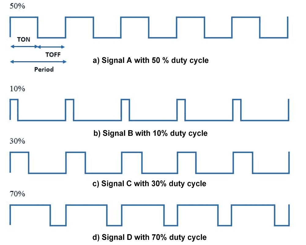
TON is the time for which signal is HIGH and TOFF is the time for which it is LOW. So terminal voltage applies to DC motor is only for TON (ON) time of Period.
E.g.
If PWM with 50% duty cycle as shown in above figure it will provide average ≈50% voltage to the motor terminal.
So in this way we get simple DC motor speed control using PWM method.
Higher duty cycle gives higher speed and lower duty cycle gives lower speed.
We can vary pulse width precisely using Microcontroller to get fine control over DC motor.
Now, we will see how to change rotational directions of DC motors.
Bidirectional DC Motor Using H-Bridge Configuration
DC motors are Bidirectional i.e. we can rotate DC motor in either direction (Clockwise/Anticlockwise) by just altering their terminal polarity. We can control DC motor direction by using H-Bridge concept as shown in below figure.
- As all switches are OFF, Motor remain disconnected i.e. OFF.
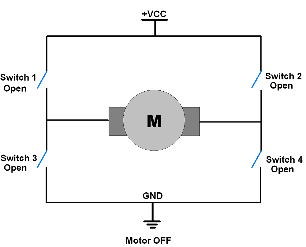
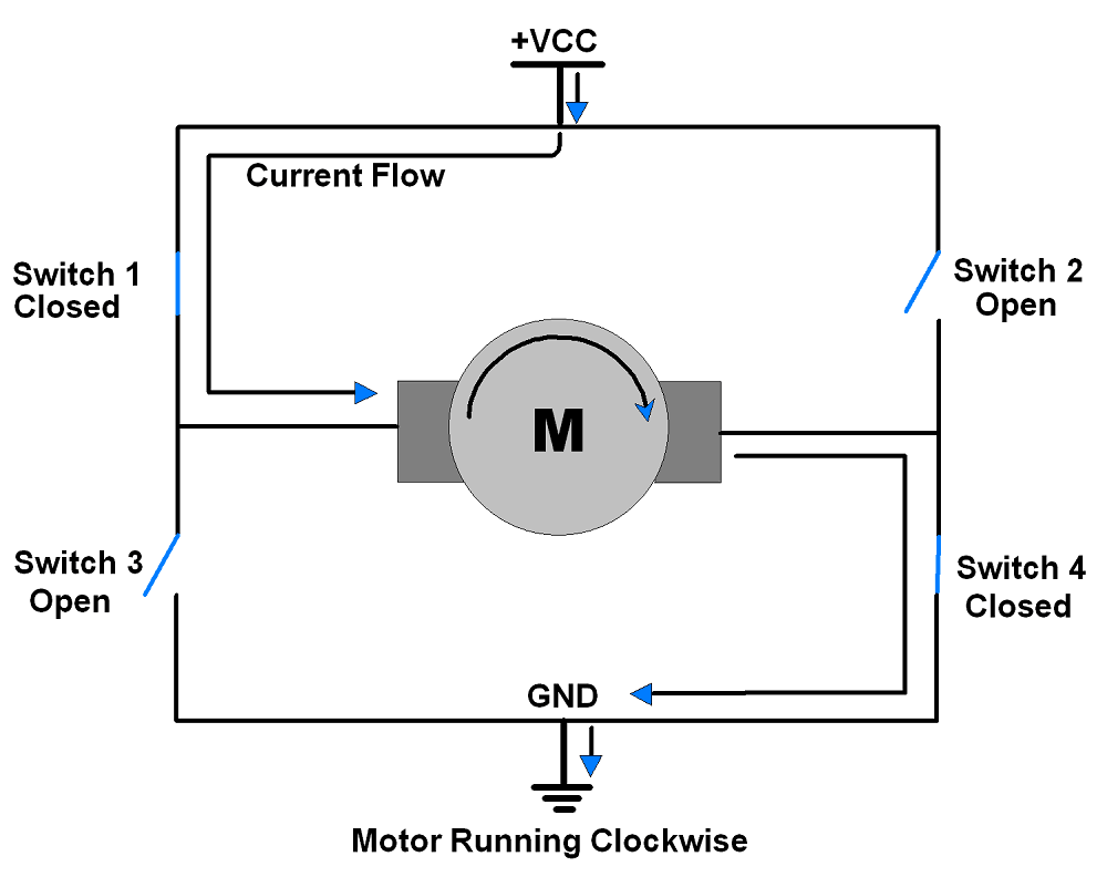
- In below figure,
Condition: Switch 1and Switch 4 are closed
Switch 2, Switch 3 are open
In this condition Motor will start rotating in Clockwise direction.
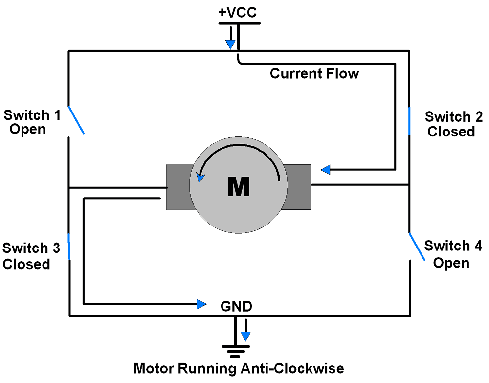
- In below figure,
Condition: Switch 3and Switch 2 are closed.
Switch 1, Switch 4 are open.
In this condition Motor will start rotating in Anticlockwise direction.
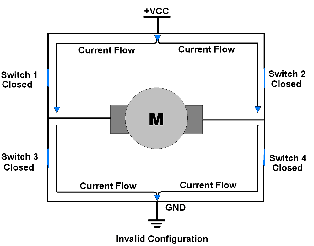
- There is another configuration when all switches are closed which is known as invalid due to its short circuit type connection as shown in below figure.
In this way we can control DC motor in both of its directions.
L293D motor driver IC can be used control DC motor movement in both directions. It has in-built H-bridge motor drive.
Types of DC Motors
- Series DC Motors: They have a high starting torque, making them suitable for heavy loads and high starting currents. However, their speed control is poor and their speed decreases as the load increases.
- Shunt DC Motors: They have a low starting torque, making them suitable for light loads and variable speed control. However, their speed remains constant under varying loads.
- Compound DC Motors: They have both series and shunt windings, which gives them a combination of high starting torque and variable speed control.
- Permanent Magnet DC Motors: They use permanent magnets instead of wound field coils to produce magnetic fields. They are small, lightweight, and efficient, but have a limited power range.
Alternate options for DC Motor
- AC Motor
- BLDC Motor
- Stepper Motor
- Servo Motor
List of DC Motor driver ICs
- L293D
- TB6612FNG
- DRV8833
- A4950
- DRV8871
- DRV8835
- DRV8838
- L298N
- SN754410
DC Motor Interfacing with Arduino
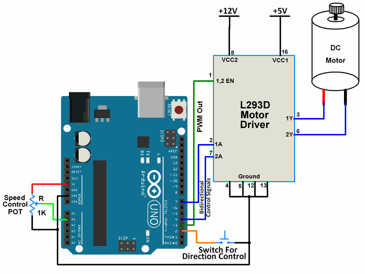
DC Motor Speed Control Code for Arduino
const int POT_input = A1;   /* assign ADC Channel */
bool d1 = HIGH;
bool d2 = LOW;

voidsetup(){
  pinMode(4, OUTPUT);  /* Motor control pin 1 */
  pinMode(7, OUTPUT);  /* Motor control pin 2 */
  pinMode(3, OUTPUT);  /* PWM pin for Speed Control */
  pinMode(2, INPUT_PULLUP); /* Interrupt pin for direction control */
 attachInterrupt(digitalPinToInterrupt(2), motor, FALLING);   /* Interrupt on falling edge on pin 2 */
}

voidloop(){
  int pwm_adc;
  pwm_adc = analogRead(POT_input); /* Input from Potentiometer for speed control */
 digitalWrite(4,d1);
 digitalWrite(7,d2);
 analogWrite(3, pwm_adc / 4);
}

voidmotor(){
  d1 = !d1;
  d2 = !d2;
  _delay_ms(200);
}
The output of the above code is to control the direction of the DC Motor using Switch and control the switch using a potentiometer
To know more about DC Motor Control using Arduino refer to this link
Examples of DC Motor interfacing
Components Used |
||
|---|---|---|
| L293D Driver L293D Driver |
X 1 | |