XBee radio family consist of various XBee RF modules. Each having different specification. Generally, XBee modules operate within ISM 2.4 GHz (Unlicensed) frequency band. XBee modules support ZigBee protocol which is based on IEEE 802.15.4 standard.
XBee modules have source/destination addressing feature with unicast and broadcast communication support. They support point to point, point to multipoint, peer to peer etc. communication topologies.
XBee modules uses DSSS (Direct Sequence Spread Spectrum) modulation technique for communication. XBee has on board features like Digital I/O pins, analog ADC (10-bit) input pins, PWM output etc. It has serial UART pins for communication with PC and Microcontrollers serially. Some XBee modules (e.g. S2C) has support for SPI interface too.
XBee Module Pin Description
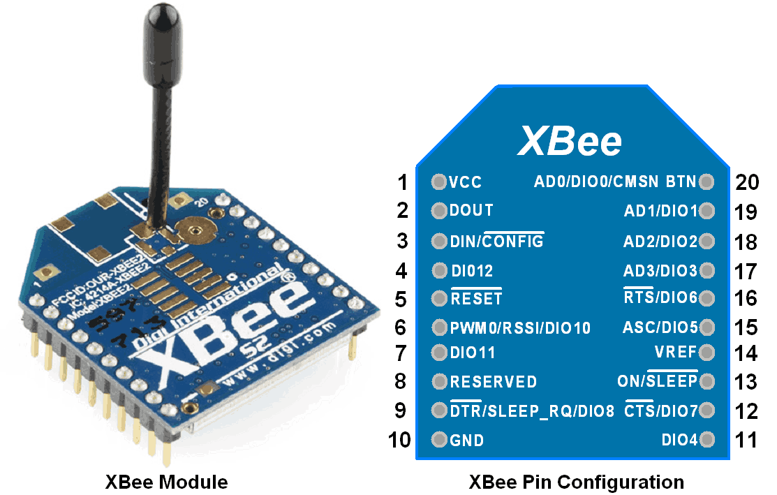
As shown in above figure of XBee module, it has 20 pins. Each pin function is described in table given below.
| Pin No. | Name | Direction | Description |
|---|---|---|---|
| 1 | VCC | - | Power Supply |
| 2 | DOUT | Output | UART Data out |
| 3 | DIN/CONFIG | Input | UART Data in |
| 4 | DO8 | Output | Digital Output 8 |
| 5 | RESET | Input | Module Reset (reset pulse >=200nS) |
| 6 | PWM0/RSSI | Output | PWM Output 0/ Received Signal Strength Indicator |
| 7 | PWM1 | Output | PWM Output 1 |
| 8 | Reserved | - | Do not connect |
| 9 | DTR/SLEEP_RQ/DI8 | Input | Sleep Control or Digital Input 8 |
| 10 | GND | - | Ground |
| 11 | AD4/DIO4 | Input / Output | Analog Input 4/ Digital I/O 4 |
| 12 | CTS/DIO7 | Input / Output | Clear-To-Send Flow Control or Digital I/O 7 |
| 13 | ON/SLEEP | Output | Module Status Indicator, High = ON, Low = SLEEP |
| 14 | VREF | Input | Reference Voltage for ADC |
| 15 | ASSOCIATE/AD5/DIO5 | Input / Output | Associated Indicator, Analog Input 5 or Digital I/O 5 |
| 16 | RTS/AD6/DIO6 | Input / Output | Request-To-Send Flow Control, Analog Input 6 or Digital I/O 6 |
| 17 | AD3/DIO3 | Input / Output | Analog Input 3 or Digital I/O 3 |
| 18 | AD2/DIO2 | Input / Output | Analog Input 2 or Digital I/O 2 |
| 19 | AD1/DIO1 | Input / Output | Analog Input 1 or Digital I/O 1 |
| 20 | AD0/DIO0 | Input / Output | Analog Input 0 or Digital I/O 0 |
Let’s see operating mode of XBee
Operating Modes
XBee modules can operate in two modes namely,
- Transparent mode (AT command)
In Transparent mode, whatever data is available on DIN pin is directly transmitted to receiver (in case of point to point) or receivers (in case of point to multipoint). - Application Programming Interface (API) mode
In API mode, data is wrapped in frame. Frame consists of Start Delimiter, Frame Length, Frame Type, Data, Checksum etc. Parameter setting and packet delivery feedback can be viewed in API mode.
As XBee module support ZigBee protocol, let’s see about ZigBee protocol in short.
ZigBee Protocol
- ZigBee Protocol is based on IEEE (Institute for Electrical and Electronics Engineers) 802.15.4 standards with additional routing and networking functionality. It is used to create Personal Area Network (PAN) using radios.
- ZigBee has mesh networking functionality. Mesh networking is used where distance between two radios is beyond their ranges. In such scenario, intermediate radio is used that will forward incoming messages to the destination and accomplish the communication between long distance radios.
ZigBee devices has three types by their function as,
- ZigBee Coordinator
- Coordinator provides network synchronization by polling nodes.
- Coordinator selects a channel and PAN ID (both 64-bit and 16-bit) to create the network. There is one Coordinator in each network since it creates network.
- Coordinator allows routers and end devices to join the network and assist in routing data.
- It also acts like a bridge to communicate with another network.
- ZigBee Router
- Router needs to join a ZigBee PAN before it can transmit, receive, or route data.
- After joining, Routers allow other routers and end devices to join the network and assist in routing/passing data by acting as intermediate radios.
- ZigBee End device
- End device cannot start network or route data.
- It always transmits or receives RF data through its parent node (Coordinator or Router).
- Due to such limited functionality, it can enter low power modes to save power.
Let’s see about PAN and Channel in ZigBee.
PAN ID (Personal Area Network ID)
- ZigBee network is known as Personal Area Network or PAN. Each network is defined with their unique PAN ID. PAN ID is common in all devices of same network.
- ZigBee devices are configured with PAN ID to join network or they can select nearby PAN ID to join with their network.
- The coordinator must select a PAN ID and channel to start a network. The coordinator and routers can allow other devices to join the network.
- The router or coordinator that allowed an end device to join the network becomes the "parent" of the end device. If the end device sleeps, the parent must be able to buffer incoming data packets which are destined for the end device until the end device is wakes up and receives the data.
Channel
ZigBee Device uses Direct Sequence Spread Spectrum (DSSS) Coding technique and operates with fixed channel.
- Sixteen channels are allocated in the 2.4 GHz band, with each channel spaced 5 MHz apart, though using only 2 MHz of bandwidth.
- XBee modules support all 16 channels and XBee-PRO modules support 14 of the 16 channel.
- The Coordinator can auto decide which PAN ID and channel to use.
Addressing
Now let’s see one important thing to know in addressing XBee devices. There are two addressing method used by XBee devices
- Short 16-bit addressing
- Long 64-bit addressing
With Unicast and Broadcast communication feature.
Short 16-bit addressing
- Short address known by ‘MY’ parameter.
- Setting the ‘DH’ parameter to zero will configure the destination address to be short 16-bit address.
- For two modules to communicate using short addressing, the Destination Address (sets in ‘DL’ parameter) of the transmitter module must match the MY parameter of the receiver as shown in below table,
| Parameter | Transmitter Module | Receiver Module |
|---|---|---|
| MY (Source Address) | 0x11 | 0x22 |
| DH (Destination Address High) | 0 | 0 |
| DL (Destination Address Low) | 0x22 | 0x11 |
Long 64-bit addressing
- In Long 64-bit addressing mode MY parameter is disabled.
- Source Address Parameters (SH & SL) and Destination Address Parameters (DH & DL) are used for communication as shown in below table,
| Parameter | Transmitter Module | Receiver Module |
|---|---|---|
| SH (Source Address High) | 0x0013A200 | 0x0013A200 |
| SL (Source Address Low) | 0x41241D5A | 0x41241CB2 |
| DH (Destination Address High) | 0x0013A200 | 0x0013A200 |
| DL (Destination Address Low) | 0x41241CB2 | 0x41241D5A |
Broadcast Mode
- By default, XBee operates in Unicast (point to point) mode of communication that supports retries of any lost message.
- Any XBee module within range will accept a packet that contains a broadcast address.
- When configured to operate in Broadcast Mode, receiving modules do not send ACKs (Acknowledgements) and transmitting modules do not automatically re-send packets as is the case in Unicast Mode.
- To send a broadcast packet to all modules regardless of 16-bit or 64-bit addressing, set the destination address of the broadcasting module as shown below.
DH (Destination High Address) = 0x00000000
DL (Destination Low Address) = 0x0000FFFF
Now let’s see how to configure XBee in either operating mode (AT command / API) and in either device function type (Coordinator / Router / End Device).
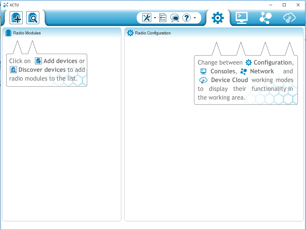
XBee Configuration
To configure XBee in either operating mode and device function type, Digi International provides a software tool known as X-CTU. Using this tool, we can configure device, test device performance and upgrade firmware.
Here we need to first download X-CTU and go through short overview of X-CTU User Guide.
We can also configure XBee devices through PC / Laptop using serial terminal easily in transparent (AT command) operating mode by using AT commands.
Note that XBee device will enter in Command mode only after getting “+++” serial command and automatically get to normal mode after an adjustable time slot.
Let’s see how to setup ZigBee network.
XBee Network
To create network, we require two or more XBee radio devices. E.g. here we take two XBee S2devices from XB24-ZB product family with two XBee USB adapter as shown below.
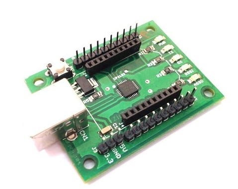
First connect both XBee devices to PC/Laptop serial port using XBee USB adapter& cable. Now open X-CTU software and click on
symbol in upper left hand side to add device.
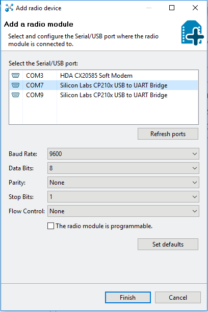
The Add radio device window will pop up in which we need to select USB port to which we have attached XBee devices. As shown in below snap.
Set Baud rate which is 9600 by default.
Set values of Data bits, parity and Stop bits.
For sake of simplicity keep all default parameters as shown in figure and click on finish. It will add selected XBee device. Do same procedure to add second XBee device.
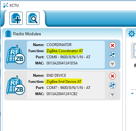
Now both devices will appear in upper left corner of X-CTU and their parameter value at right hand side as shown in below figure.
- Here we have configured one XBee device as Coordinator.
- And another one as End Device.
Both are configured in transparent (AT command) mode.
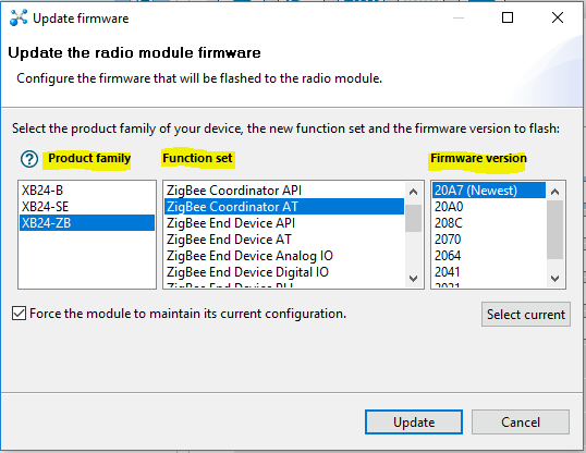
To configure XBee device in another operating mode and function set click on update
symbol besides the upper right hand side. Update Firmware window will pop up as shown in below figure, where we can select,
- Product family of XBee device.
- Function set to select required operating mode and function type of XBee device.
- And firmware version.
After updating XBee devices with correct firmware, we must ensure at least three parameters of XBee devices given below
- Baud rate should be same for each device.
- PAN ID should be unique for all XBee devices in same n/w.
- Operating Channel should be same for all devices in same n/w.
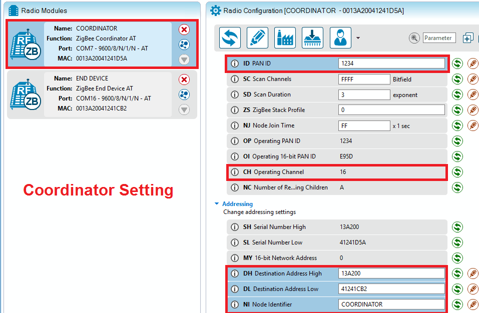
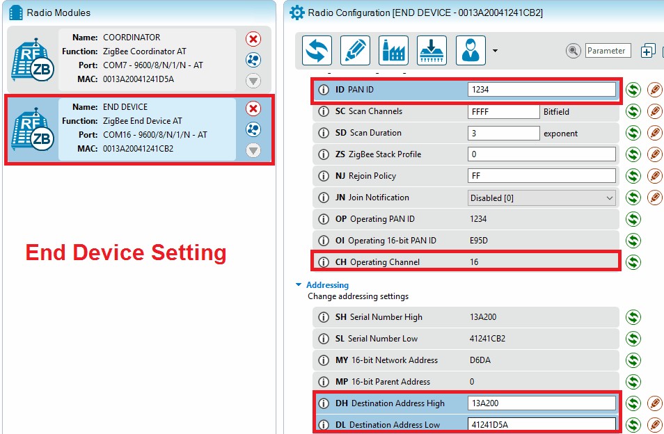
Now let’s set XBee parameters i.e. PAN ID, Channel (CH) and Communicate in Unicast mode using long 64-bit addressing mode for both XBee devices as shown in below figure.
- Here we are setting PAN ID = 1234. Coordinator will select channel.
- For long 64-bit addressing mode we are setting Coordinator Source Address (SH &SL) parameters in End Device Destination Address (DH &DL) parameters and vice versa.
- Don’t forget to keep Baud rate same of devices in the same network.
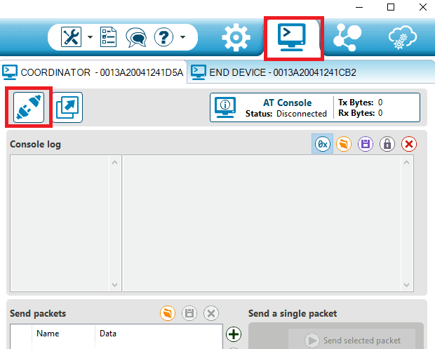
Now to test communication, open the console by clicking
symbol shown in upper right corner of X-CTU window and click on open to open console as shown in below figure.
Now type message from Coordinator console log, it will appear at end device console log and vice versa as seen in below GIF.
API Operation
Now let’s see packet based Application Programming Interface (API) mode.
- In API mode, data is structured in well-defined frame.
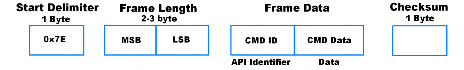
- Generally, Frame starts with one-byte Start Delimiter (0x7E), then Frame Length, Frame Type, Frame Data and ends with Checksum.
- Any incoming data before Start Delimiter is discarded.
- And if checksum is not correct then data is discarded.
- Frame Length is 2-3-byte data which indicate frame length. It is measured from Frame Type till Checksum in bytes.
- Frame Type is a one-byte command ID represent the frame type like Transmit request frame, AT command frame, Remote AT command frame, Modem Status frame, Transmit status frame etc.
- Frame Data is the actual data or command to be send.
- Checksum is a one-byte data calculated and verified on non-escaped data. It is calculated by adding all bytes (Not including Start delimiter and Frame length,), keeping only the lowest 8 bits of the result and subtract it from 0xFF.
Let’s see example of AT Command Frame
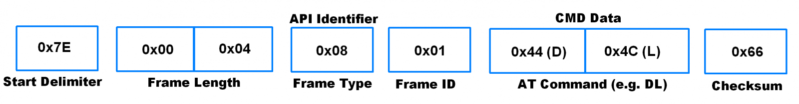
Here,
Frame Length = Length of (Frame Type + Frame ID + AT Command) in Bytes
Checksum = 0xFF – (Frame Type + Frame ID + AT Command)
= 0xFF – (0x08 + 0x01 + 0x44 + 0x4C) = 0x66.
As shown in above figure we can check API frame structure and example of AT command frame. In example, there we have checked DL parameter of XBee device, for which we have to send above AT Command Frame i.e. we have to send below data serially to XBee device,
0x7E 0x00 0x04 0x08 0x01 0x44 0x4C 0x66.
Note that depending on API identifier/Frame Type, CMD Data gets sectored in Data, Option, Parameter value, Digital value, analog value etc.
Note: - In API operation (with escape) mode, when sending or receiving a UART data frame, specific data values must be escaped (flagged) so they do not interfere with the UART or UART data frame operation. To escape an interfering data byte, insert 0x7D and follow it with the byte to be escaped XORed with 0x20.
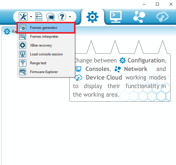
API Frame Generator in X-CTU
X-CTU has API frame generator tool through which we can generate API frames. Open X-CTU and Select tools -> Frames generator in X-CTU as shown in below figure.
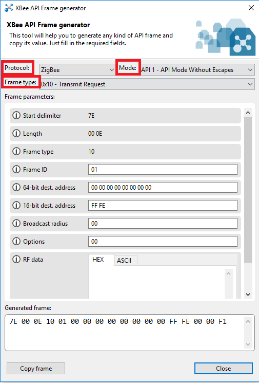
Upon clicking on Frames generator XBee API Frame generator window will pop up where we can generate API frames based on Protocol, Mode and Frame type as shown in below figure.
Now let’s see about ADC and Digital line support of XBee
ADC and Digital I/O Pins
XBee device has 10-bit ADC and Digital I/O line passing support. Specific XBee device pins can be configured to one of following function,
- ADC
- When XBee pin configured as ADC it takes analog input with respect to Vref pin of XBee and gives 10-bit ADC value in I/O Sample Data frame (0x92).
- ADC Vref is varying according to XBee Model refer ADC Voltages - Digital Input
- When XBee pin configured as Digital Input pin it takes digital input on this pin and writes it to I/O Sample Data frame. - Digital Output Low
- XBee device can configure their Digital enabled pins as Output Low (0) with this function. - Digital Output High
- XBee device can configure their Digital enabled pins as Output High (1) with this function.
I/O data begin with header in frame and after header; I/O sample data is present in frame as shown in below figure.
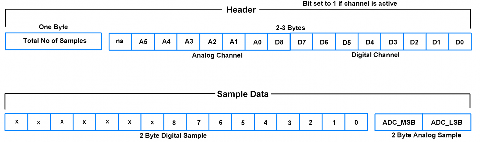
Header indicates number of samples and which channel is active at a time; whereas sample data consists of actual analog and digital data.
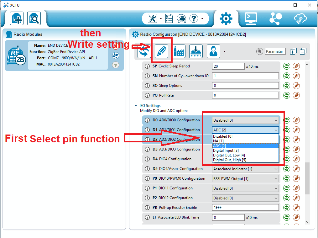
Configuring XBee Pins
Let’s see how to configure any specific XBee pin function from XCTU tool
Select the XBee pin to be configured.
Then select the function for that pin as shown in below image and click on write setting
Now let’s see about I/O Sampling
I/O Sampling
XBee devices have ability to monitor and sample all analog and digital I/O lines. To read I/O samples from remote device, parent device must have API mode enabled. I/O sampling is mostly used to request analog and digital samples from XBee end.
There are three ways to obtain I/O samples, either locally or remotely:
- Queried Sampling
In Queried sampling, parent XBee device sends command (IS) to remote XBee device. XBee end device samples all the enabled digital and analog i/p channels and sends it to XBee parent device. - Periodic Sampling
Periodic sampling allows XBee device to sample all the enabled digital and analog i/p channels and transmit it periodically to parentXBee device. Period is set by IR command. - Change Detection Sampling
This sampling is allowed only for digital i/p channels of XBee device. By configuring any digital i/p pin for change detection sampling, XBee device is able to send I/O samples whenever state of that digital pin changes i.e. from HIGH to LOW or LOW to HIGH.
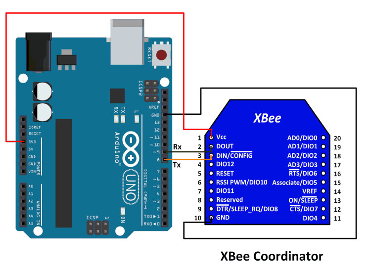
Connection Diagram of Xbee S2 Module with Arduino
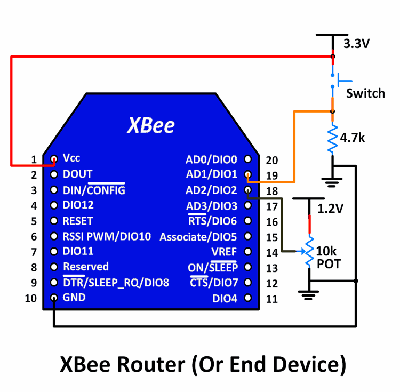
Connection Diagram of XBee Router (At End device)
XBee S2 (ZigBee) Code for Arduino UNO
#include <XBee.h>
#include <SoftwareSerial.h>

#define ssRX  9 /* Rx pin for software serial */
#define ssTX  8 /* Tx pin for software serial */

/* Create object named xbee_ss of the class SoftwareSerial */
SoftwareSerial xbee_ss(ssRX, ssTX); /* Define pins for software serial instance named xbee-ss(any name of your choice) to be connected to xbee */
/* ssTx of Arduino connected to Din (pin 3 of xbee) */
/* ssRx of Arduino connected to Dout (pin 2 of xbee) */

XBee xbee = XBee(); /* Create an object named xbee(any name of your choice) of the class XBee */

ZBRxIoSampleResponse ioSamples = ZBRxIoSampleResponse();
/* Create an object named ioSamples(any name of your choice) of the class ZBRxIoSampleResponse */

void setup() {
  Serial.begin(9600); /* Define baud rate for serial communication */
  xbee_ss.begin(9600); /* Define baud rate for software serial communication */
  xbee.setSerial(xbee_ss); /* Define serial communication to be used for communication with xbee */
  /* In this case, software serial is used. You could use hardware serial as well by writing "Serial" in place of "xbee_ss" */
  /* For UNO, software serialis required so that we can use hardware serial for debugging and verification */
  /* If using a board like Mega, you can use Serial, Serial1, etc. for the same, and there will be no need for software serial */
}

void loop() {
  xbee.readPacket(); /* Read until a packet is received or an error occurs */

  if(xbee.getResponse().isAvailable()) /* True if response has been successfully parsed and is complete */
  {
    if(xbee.getResponse().getApiId()==ZB_IO_SAMPLE_RESPONSE) /* If response is of IO_Sample_response type */
    {
      xbee.getResponse().getZBRxIoSampleResponse(ioSamples); /* Get the IO Sample Response */

      Serial.print("Received I/O Sample from: ");

      Serial.print(ioSamples.getRemoteAddress64().getMsb(), HEX); /* DH(in HEX format) of the sending device */
      Serial.print(ioSamples.getRemoteAddress64().getLsb(), HEX); /* DL(in HEX format) of the sending device */
      Serial.println("");

      if (ioSamples.containsAnalog()) { /* If Analog samples present in the response */
        Serial.println("Sample contains analog data");
      }

      if (ioSamples.containsDigital()) { /* If Digital samples present in the response */
        Serial.println("Sample contains digtal data");
      }

      /* Loop for identifying the analog samples present in the received sample data and to print it */
      for (int i = 0; i <= 4; i++) { /* Only 4 Analog channels */
        if (ioSamples.isAnalogEnabled(i)) { /* Check Analog channel mask to see if the any pin is enabled for analog input sampling */
          Serial.print("Analog (AI");
          Serial.print(i, DEC);
          Serial.print(") is ");
          Serial.println(ioSamples.getAnalog(i), DEC);
        }
      }

      for (int i = 0; i <= 12; i++) { /* 12 Digital IO lines */
        if (ioSamples.isDigitalEnabled(i)) { /* Check Digital channel mask to see if any pin is enabled for digital IO sampling  */
          Serial.print("Digital (DI");
          Serial.print(i, DEC);
          Serial.print(") is ");
          Serial.println(ioSamples.isDigitalOn(i), DEC);
        }
      }
    }
    else
    {
      Serial.print("Expected I/O Sample, but got ");
      Serial.print(xbee.getResponse().getApiId(), HEX); /* Print response received instead of IO_Sample_Response */
    }
  }
  else if (xbee.getResponse().isError()) { /* If error detected, print the error code */
    Serial.print("Error reading packet.  Error code: ");
    Serial.println(xbee.getResponse().getErrorCode());
  }
}
Please check this guide for more details, output and video
Examples of XBee interfacing
Components Used |
||
|---|---|---|
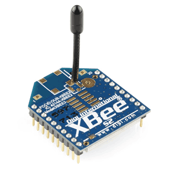
| XBee S2 Module XBee is a radio module developed by Digi International. It is popular wireless transceiver used to send or receive data. It is used for low data rate, low power over short distance wireless communication applications such as Home Automation, Wireless sensor n/w, Industrial control, Medical data collection, Building automation etc. |
X 1 | |
Downloads |
||
|---|---|---|
|
|
XBee Datasheet | Download |