Introduction
GPS receivers are generally used in smartphones, fleet management system, military etc. for tracking or finding location.
Global Positioning System (GPS) is a satellite-based system that uses satellites and ground stations to measure and compute its position on Earth.
GPS is also known as Navigation System with Time and Ranging (NAVSTAR) GPS.
GPS receiver needs to receive data from at least 4 satellites for accuracy purpose. GPS receiver does not transmit any information to the satellites.
This GPS receiver is used in many applications like smartphones, Cabs, Fleet management etc.
How GPS Works
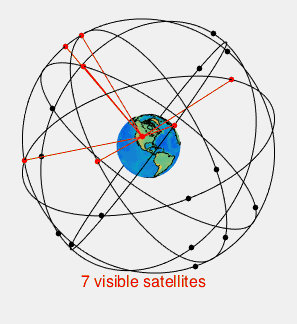
GPS receiver uses a constellation of satellites and ground stations to calculate accurate location wherever it is located.
These GPS satellites transmit information signal over radio frequency (1.1 to 1.5 GHz) to the receiver. With the help of this received information, a ground station or GPS module can compute its position and time.
How GPS Receiver Calculates its Position and Time
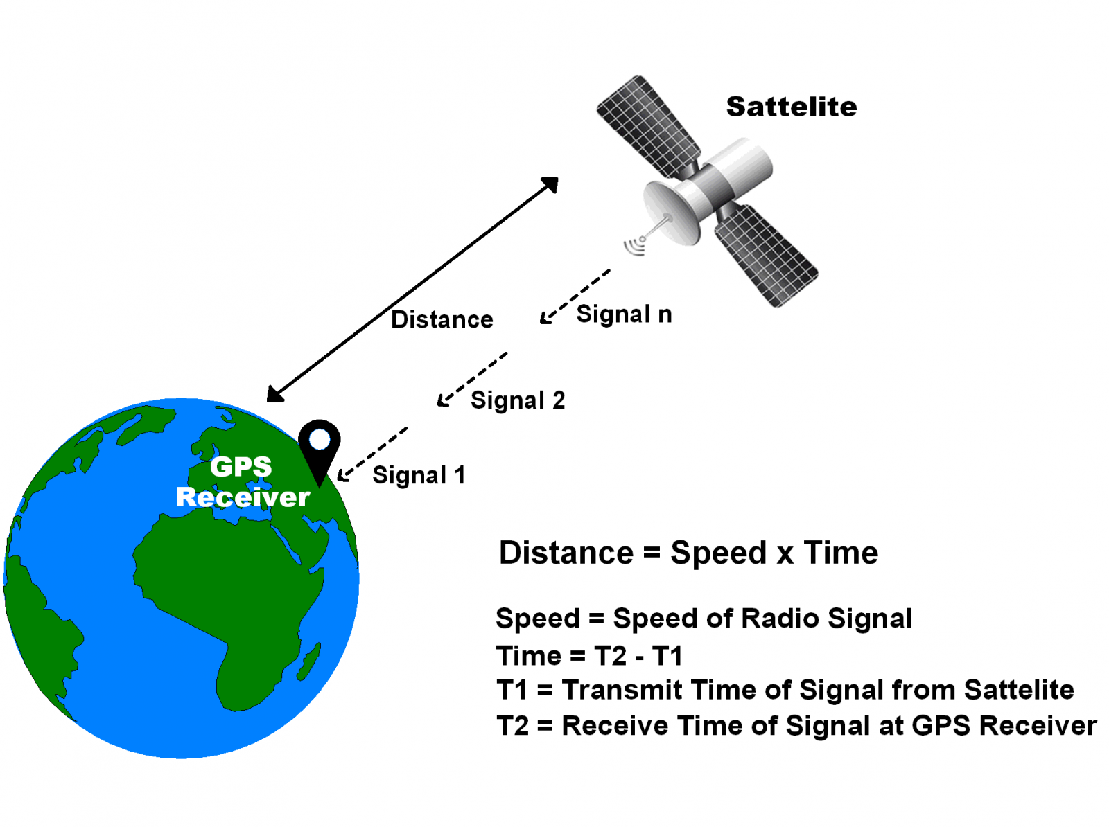
GPS receiver receives information signals from GPS satellites and calculates its distance from satellites. This is done by measuring the time required for the signal to travel from satellite to the receiver.
Where,
Speed = Speed of Radio signal which is approximately equal to the speed of light i.e.
Time = Time required for a signal to travel from the satellite to the receiver.
By subtracting the sent time from the received time, we can determine the travel time.
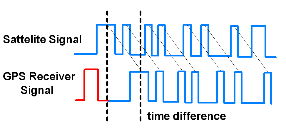
To determine distance, both the satellite and GPS receiver generate the same pseudocode signal at the same time.
The satellite transmits the pseudocode; which is received by the GPS receiver.
These two signals are compared and the difference between the signals is the travel time.
Now, if the receiver knows the distance from 3 or more satellites and their location (which is sent by the satellites), then it can calculate its location by using Trilateration method.
GPS Module
GPS receiver module gives output in standard (National Marine Electronics Association) NMEA string format. It provides output serially on Tx pin with default 9600 Baud rate.
This NMEA string output from GPS receiver contains different parameters separated by commas like longitude, latitude, altitude, time etc. Each string starts with ‘$’ and ends with carriage return/line feed sequence.
E.g.
$GPGGA,184237.000,1829.9639,N,07347.6174,E,1,05,2.1,607.1,M,-64.7,M,,0000*7D
$GPGSA,A,3,15,25,18,26,12,,,,,,,,5.3,2.1,4.8*36
$GPGSV,3,1,11,15,47,133,46,25,44,226,45,18,37,238,45,26,34,087,40*72
$GPGSV,3,2,11,12,27,184,45,24,02,164,26,29,58,349,,05,26,034,*7F
$GPGSV,3,3,11,21,25,303,,02,11,071,,22,01,228,*40
$GPRMC,184237.000,A,1829.9639,N,07347.6174,E,0.05,180.19,230514,,,A*64
Pin Description
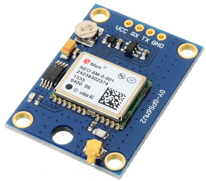
VCC: Power Supply 3.3 – 6 V
GND: Ground
TX: Transmit data serially which gives information about location, time etc.
RX: Receive Data serially. It is required when we want to configure GPS module.
Check GPS module
Before Interfacing the GPS module with the PIC18F4550 microcontroller, we can check the output of GPS module. From that string, we can extract information like longitude, latitude, and time which is helpful to find location and timing information.
To do this, connect this GPS module to the PC via USB to Serial converter or DB9 connector. Also, it is necessary to keep the antenna of GPS module on proper location.
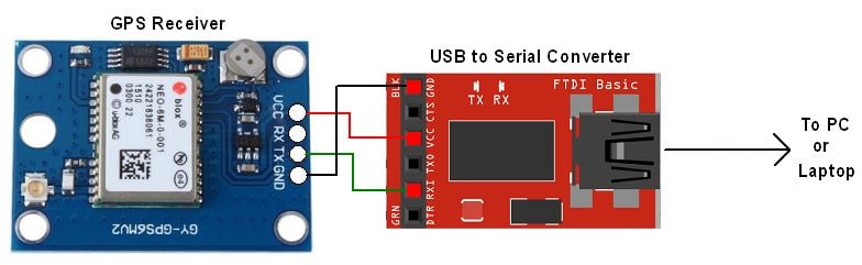
Now open any serial terminal e.g. Realterm, Hyper terminal, Putty, etc. on a PC/laptop.
Open the PORT with a 9600 baud rate.
The terminal will show data coming from the GPS receiver module.
The output data from the GPS receiver module displaying on a serial terminal as follows.
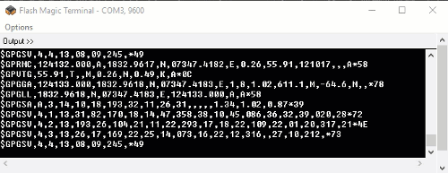
In the above string, the NMEA string starting with “$GPGGA” is most popularly used. It provides us Time, Longitude, Latitude and Altitude along with directions. This information is helpful to find Time and Location.
E.g.
$GPGGA,184241.000,1829.9639,N,07347.6174,E,1,05,2.1,607.1,M,-64.7,M,,0000*7C
| Name | Example | Units | Description |
| Message ID | $GPGGA | GGA Protocol Header | |
| UTC Time | 184241.000 | hhmmss.sss | |
| Latitude | 1829.9639 | ddmm.mmmm | |
| N/S Indicator | N | N=North, S=South | |
| Longitude | 07347.6174 | dddmm.mmmm | |
| E/W Indicator | E | E=East, W=West | |
| Position Fix Indicator | 1 | Fix GPS SPS mode | |
| Satellites Used | 05 | Range 0 to 12 | |
| HDOP | 2.1 | Horizontal Dilution of Precision | |
| MSL Altitude | 607.1 | Meters | Mean Sea Level |
| Units | M | Meters | |
| Geoid Separation | 64.7 | Meters | |
| Units | M | Meters | |
| Age of Diff. Corr. | - | Null field if DGPS is not used | |
| Diff. Ref Station ID | 0000 | ||
| Checksum | *7C | ||
| Carriage return Line Feed | <CR><LF> | End of message transmission |
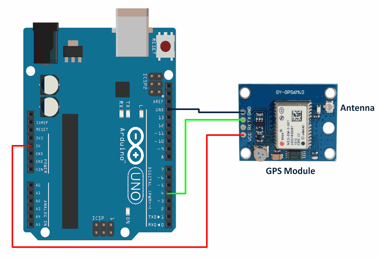
Connection Diagram of GPS Module with Arduino Uno
GPS Code for Arduino Uno
Here, we will be using Mikal Hart’s TinyGPSPlus library from GitHub.
Download this library from here.
#include <TinyGPS++.h>
#include <SoftwareSerial.h>
/* Create object named bt of the class SoftwareSerial */
SoftwareSerial GPS_SoftSerial(4, 3);/* (Rx, Tx) */
/* Create an object named gps of the class TinyGPSPlus */
TinyGPSPlus gps;

volatile float minutes, seconds;
volatile int degree, secs, mins;

void setup() {
  Serial.begin(9600);	/* Define baud rate for serial communication */
  GPS_SoftSerial.begin(9600);	/* Define baud rate for software serial communication */
}

void loop() {
        smartDelay(1000);	/* Generate precise delay of 1ms */
        unsigned long start;
        double lat_val, lng_val, alt_m_val;
        uint8_t hr_val, min_val, sec_val;
        bool loc_valid, alt_valid, time_valid;
        lat_val = gps.location.lat();	/* Get latitude data */
        loc_valid = gps.location.isValid();	/* Check if valid location data is available */
        lng_val = gps.location.lng();	/* Get longtitude data */
        alt_m_val = gps.altitude.meters();	/* Get altitude data in meters */
        alt_valid = gps.altitude.isValid();	/* Check if valid altitude data is available */
        hr_val = gps.time.hour();	/* Get hour */
        min_val = gps.time.minute(); 	/* Get minutes */
        sec_val = gps.time.second();	/* Get seconds */
        time_valid = gps.time.isValid();	/* Check if valid time data is available */
        if (!loc_valid)
        {
          Serial.print("Latitude : ");
          Serial.println("*****");
          Serial.print("Longitude : ");
          Serial.println("*****");
        }
        else
        {
          DegMinSec(lat_val);
          Serial.print("Latitude in Decimal Degrees : ");
          Serial.println(lat_val, 6);
          Serial.print("Latitude in Degrees Minutes Seconds : ");
          Serial.print(degree);
          Serial.print("\t");
          Serial.print(mins);
          Serial.print("\t");
          Serial.println(secs);
          DegMinSec(lng_val);	/* Convert the decimal degree value into degrees minutes seconds form */
          Serial.print("Longitude in Decimal Degrees : ");
          Serial.println(lng_val, 6);
          Serial.print("Longitude in Degrees Minutes Seconds : ");
          Serial.print(degree);
          Serial.print("\t");
          Serial.print(mins);
          Serial.print("\t");
          Serial.println(secs);
        }
        if (!alt_valid)
        {
          Serial.print("Altitude : ");
          Serial.println("*****");
        }
        else
        {
          Serial.print("Altitude : ");
          Serial.println(alt_m_val, 6);
        }
        if (!time_valid)
        {
          Serial.print("Time : ");
          Serial.println("*****");
        }
        else
        {
          char time_string[32];
          sprintf(time_string, "Time : %02d/%02d/%02d \n", hr_val, min_val, sec_val);
          Serial.print(time_string);
        }
}

static void smartDelay(unsigned long ms)
{
  unsigned long start = millis();
  do
  {
    while (GPS_SoftSerial.available())	/* Encode data read from GPS while data is available on serial port */
      gps.encode(GPS_SoftSerial.read());
/* Encode basically is used to parse the string received by the GPS and to store it in a buffer so that information can be extracted from it */
  } while (millis() - start < ms);
}

void DegMinSec( double tot_val)		/* Convert data in decimal degrees into degrees minutes seconds form */
{
  degree = (int)tot_val;
  minutes = tot_val - degree;
  seconds = 60 * minutes;
  minutes = (int)seconds;
  mins = (int)minutes;
  seconds = seconds - minutes;
  seconds = 60 * seconds;
  secs = (int)seconds;
}
The output of the above code will be the latitude, longitude, altitude, and time data obtained from a GPS module. The data will be printed in both decimal degree and degrees minutes seconds format using the DegMinSec function. The output will be continuously displayed on the serial monitor with a delay of 1 second between each update. If the GPS module is unable to provide valid data for a particular value, the output will display "*****" instead of the actual value.
To check the output using Arduino and know more using this link
Examples of GPS Receiver interfacing
- GPS Receiver Module Interfacing with PIC18F4550
- GPS Receiver Module Interfacing with ATmega16
- GPS Receiver Module Interfacing with Arduino
- GPS Receiver Module Interfacing with TI Launchpad
- GPS Receiver Module Interfacing with LPC2148
- GPS Receiver Module Interfacing with 8051
- GPS Receiver Module Interfacing with Raspberry Pi
Components Used |
||
|---|---|---|
| em-506 GPS Module EM-506 is a GPS receiver module by USGlobalSat. It provides high sensitivity and performance even in dense areas. |
X 1 | |
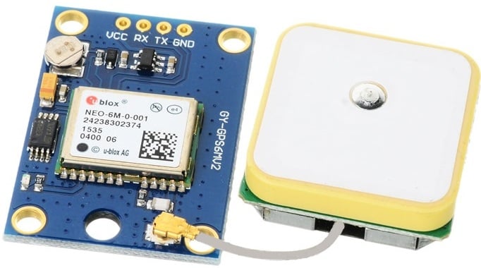
| Ublox NEO-6m GPS Ublox Neo 6m GPS |
X 1 | |
Downloads |
||
|---|---|---|
|
|
GPS Basics | Download |