Overview of Accelerometer
An accelerometer is an electromechanical device that measures the force of acceleration due to gravity in g unit.
It can be used for tilt sensing applications (For example: In mobile phones, gaming applications, etc).
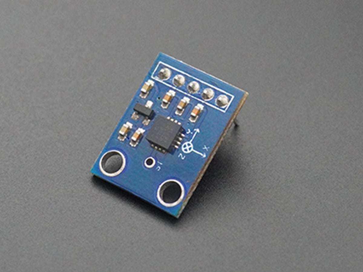
The ADXL335 measures acceleration along X, Y, and Z axes.
It gives analog voltage output proportional to the acceleration along the 3 axes.
These voltages can be converted to a digital signal using ADC and then processed by the microcontroller to find out the tilt.
For more information about the ADXL335 accelerometer and how to use it, refer to the topic ADXL335 Accelerometer Module in the sensors and modules section.
For information about ADC in ATmega16 and how to use it, refer to the topic ADC in AVR ATmega16/ATmega32 in the ATmega inside section.
Interfacing Accelerometer ADXL335 with AVR ATmega16
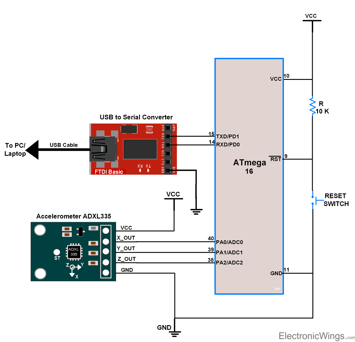
- As the module has an analog output. we will measure it using ADC channels of ATmega16.
- ATmega16 has ADC pins on its PORT A and it has 8 input channels.
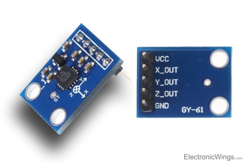
- So we will connect X, Y, and Z analog output of the ADXL335 module to three input ADC channels of ATmega16, say channel0, channel1, and channel2 respectively.
- And after reading ADC values of X, Y, and Z from the module, we will send it to the PC/Laptop over USART.
Connection Diagram of ADXL335 with ATmega16/32
Accelerometer ADXL335 Code for ATmega16/32
/*
 * ATmega16_Accelerometer.c
 * http://www.electronicwings.com
 *
 */

#define F_CPU 8000000UL		/* Define CPU clock Frequency 8MHz */
#include <avr/io.h>		/* Include AVR std. library file */
#include <util/delay.h>		/* Include defined delay header file */
#include <stdio.h>		/* Include standard i/o library file */
#include "USART_RS232_H_file.h"	/* Include USART header file */


void ADC_Init()			/* ADC Initialization function */
{
	DDRA = 0x00;		/* Make ADC port as input */
	ADCSRA = 0x87;		/* Enable ADC, with freq/128  */
	ADMUX = 0x40;		/* Vref: Avcc, ADC channel: 0 */
}

int ADC_Read(char channel)	/* ADC Read function */
{
	ADMUX = 0x40 | (channel & 0x07);/* set input channel to read */
	ADCSRA |= (1<<ADSC);	/* Start ADC conversion */
	while (!(ADCSRA & (1<<ADIF)));	/* Wait until end of conversion by polling ADC interrupt flag */
	ADCSRA |= (1<<ADIF);	/* Clear interrupt flag */
	_delay_ms(1);		/* Wait a little bit */
	return ADCW;		/* Return ADC word */
}

int main(void)
{
	char buffer[50];
	int ADC_X_VALUE,ADC_Y_VALUE,ADC_Z_VALUE;
	USART_Init(9600);	/* Initialize USART with 9600 Baud rate */
	ADC_Init();		/* Initialize ADC */

	while(1)
	{
		ADC_X_VALUE = ADC_Read(0);	/* Read X, Y, Z axis ADC value */
		ADC_Y_VALUE = ADC_Read(1);
		ADC_Z_VALUE = ADC_Read(2);

	sprintf(buffer,"X = %d\t Y = %d\t Z = %d\n\r",ADC_X_VALUE,ADC_Y_VALUE,ADC_Z_VALUE);
		USART_SendString(buffer);	/* Send X, Y, Z value Serially */
		_delay_ms(30);
	}
}
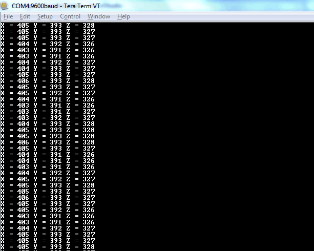
Output Window
On PC/Laptop’s serial terminal application, we can see directly X, Y, Z’s ADC values as shown in the below figure. For testing tilt the module in X and Y direction and observe the changes in X and Y values.
- If we tilt the module on X-axis, we get variations in X and Z values whereas Y will remain nearly constant.
- If we tilt the module on Y-axis, we get variations in Y and Z values whereas Y will remain nearly constant.
Output window of ADC values.
Accelerometer ADXL335 Code for ATmega16/32
Calculate the angle of tilt or inclination using ATmega16 and print on the serial monitor
/*
 * ATmega16_Accelerometer.c
 * http://www.electronicwings.com
 *
 */

#define F_CPU 8000000UL		/* Define CPU clock Frequency e.g. here its 8MHz */
#include <avr/io.h>			/* Include AVR std. library file */
#include <util/delay.h>		/* Include defined delay header file */
#include <stdlib.h>			/* Include standard library file */
#include <math.h>			/* Include math header file */
#include "USART_RS232_H_file.h"	/* Include USART header file */


void ADC_Init()			/* ADC InitialiAzouttion function */
{
	DDRA = 0x00;		/* Make ADC port as input */
	ADCSRA = 0x87;		/* Enable ADC, with freq/128  */
	ADMUX = 0x40;		/* Vref: Avcc, ADC channel: 0 */
}

int ADC_Read(char channel)	/* ADC Read function */
{
	ADMUX = 0x40 | (channel & 0x07);	/* set input channel to read */
	ADCSRA |= (1<<ADSC);				/* Start ADC conversion */
	while (!(ADCSRA & (1<<ADIF)));		/* Wait until end of conversion by polling ADC interrupt flag */
	ADCSRA |= (1<<ADIF);				/* Clear interrupt flag */
	_delay_ms(1);						/* Wait a little bit */
	return ADCW;						/* Return ADC word */
}

void SendSerial(char* str, double value, char unit)
{
	char buffer[10];
	dtostrf(value,4,2,buffer);
	USART_SendString(str);		/* Send Name string */
	USART_SendString(buffer); 	/* Send value */
	USART_TxChar(unit);			/* Send unit char */
	USART_TxChar('\t');			/* Send tab char */
	_delay_ms(10);
}

int main(void)
{
	int ADC_X_VALUE,ADC_Y_VALUE,ADC_Z_VALUE;
	double Axout,Ayout,Azout,theta, psy, phi,roll,pitch,yaw;
	USART_Init(9600);	/* Initialize USART with 9600 Baud rate */
	ADC_Init();			/* Initialize ADC */

	while(1)
	{
		ADC_X_VALUE = ADC_Read(0);  /* Read X, Y, Z axis ADC value */
		ADC_Y_VALUE = ADC_Read(1);
		ADC_Z_VALUE = ADC_Read(2);

		/* Convert values in g unit */
		Axout = (((double)(ADC_X_VALUE*5)/1.024)-1700.0)/330.0;
		Ayout = (((double)(ADC_Y_VALUE*5)/1.024)-1700.0)/330.0;
		Azout = (((double)(ADC_Z_VALUE*5)/1.024)-1700.0)/330.0;

		/* Calculate angles */
		theta = atan(Axout/(sqrt((pow (Ayout,2.0))+(pow (Azout,2.0)))))*57.29577951;
		psy =  atan(Ayout/(sqrt((pow (Axout,2.0))+(pow (Azout,2.0)))))*57.29577951;
		phi =  atan((sqrt((pow (Ayout,2.0))+(pow (Axout,2.0))))/Azout)*57.29577951;

		roll = (atan2(Ayout,Azout))*57.29577951+180;
		pitch =  (atan2(Azout,Axout))*57.29577951+180;
		yaw =  (atan2(Axout,Ayout))*57.29577951+180;

		SendSerial("Axout = ",Axout,'g');/* Send All value */
		SendSerial("Ayout = ",Ayout,'g');
		SendSerial("Azout = ",Azout,'g');

		SendSerial("Theta = ",theta,248);
		SendSerial("Psy = ",psy,248);
		SendSerial("Phi = ",phi,248);

		SendSerial("Roll = ",roll,248);
		SendSerial("Pitch = ",pitch,248);
		SendSerial("Yaw = ",yaw,248);

		USART_SendString("\n\r");
	}
}
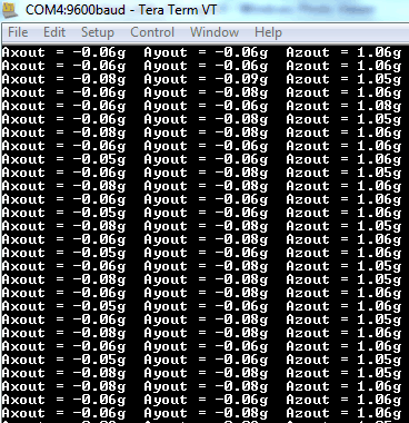
Output Window
- Acceleration in g unit:
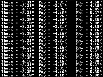
2. Angle of Inclination
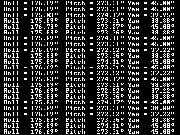
3. Angle of Rotation
Video of Object Movement using an Accelerometer with ATmega16/32
Components Used |
||
|---|---|---|
| ATmega 16 ATmega 16 |
X 1 | |
| Atmega32 Atmega32 |
X 1 | |
| ADXL335 Accelerometer Module Accelerometer ADXL335 sensor measures acceleration of gravity. It is used to measure the angle of tilt or inclination in application systems such as in mobile devices, gaming applications, laptops, digital cameras, aeroplanes etc. |
X 1 | |
| CP2103 USB TO UART BRIDGE CP2103 is single chip USB to UART Bridge. It supports USB 2.0 protocol. |
X 1 | |