Overview of GLCD 128x64
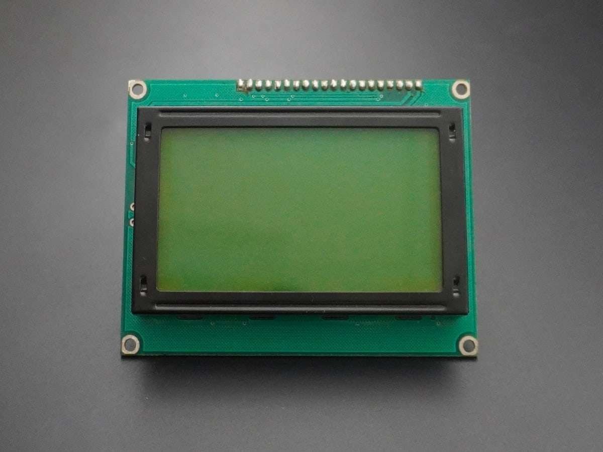
GLCD is a display device that can be used in embedded systems for displaying data and/or images/custom characters.
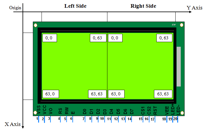
- Basically, a 128x64 Graphical LCD is a matrix of pixels.
- Each pixel is accessed by their X and Y address.
- We can simply visualize any pixel by making its value HIGH (1).
Hence, we can make any graphical design pixel by pixel using GLCD.
To get familiar with GLCD pins and their functions refer to GLCD 128x64.
Programming GLCD
Let's program the AVR ATmega16 microcontroller to print text characters on GLCD JHD12864E.
Initialization
To initialize the display, we need to do the below steps,
- Send Display OFF command i.e. 0x3E
- Send Y address e.g. here 0x40 (Start address).
- Send X address (Page) e.g. here 0xB8 (Page0).
- Send Z address (Start line) e.g. here 0xC0 (from 0th line).
- Now send Display ON command i.e. 0x3F
GLCD_Init function
Input arguments: It has no input arguments.
Return type: It does not return any data type.
void GLCD_Init()			/* GLCD initialize function */
{
	Data_Port_Dir = 0xFF;
	Command_Port_Dir = 0xFF;
	/* Select both left & right half of display & Keep reset pin high */
	Command_Port |= (1 << CS1) | (1 << CS2) | (1 << RST);
	_delay_ms(20);
	GLCD_Command(0x3E);		/* Display OFF */
	GLCD_Command(0x40);		/* Set Y address (column=0) */
	GLCD_Command(0xB8);		/* Set x address (page=0) */
	GLCD_Command(0xC0);		/* Set z address (start line=0) */
	GLCD_Command(0x3F);		/* Display ON */
}
Command Write
To write a command do the below steps
- Send command on data pins.
- Make RS = 0 (Command Register) and RW = 0 (Write Operation).
- Make High to Low transition on Enable pin of min. 1us period.
GLCD_Command function
Input arguments: It has an input argument of Command.
Return type: It does not return any data type.
void GLCD_Command(char Command)		/* GLCD command function */
{
	Data_Port = Command;		/* Copy command on data pin */
	Command_Port &= ~(1 << RS);	/* Make RS LOW for command register*/
	Command_Port &= ~(1 << RW);	/* Make RW LOW for write operation */
	Command_Port |=  (1 << EN);	/* HIGH-LOW transition on Enable */
	_delay_us(5);
	Command_Port &= ~(1 << EN);
	_delay_us(5);
}
Data Write
To write data do the below commands
- Send Data on data pins.
- Make RS = 1 (Data Register) and RW = 0 (Write Operation).
- Make High to Low transition on Enable pin of min 1 us period.
GLCD_Data function
Input arguments: It has input argument Data.
Return type: It does not return any data type.
void GLCD_Data(char Data)		/* GLCD data function */
{
	Data_Port = Data;		/* Copy data on data pin */
	Command_Port |=  (1 << RS);	/* Make RS HIGH for data register */
	Command_Port &= ~(1 << RW);	/* Make RW LOW for write operation */
	Command_Port |=  (1 << EN);	/* HIGH-LOW transition on Enable */
	_delay_us(5);
	Command_Port &= ~(1 << EN);
	_delay_us(5);
}
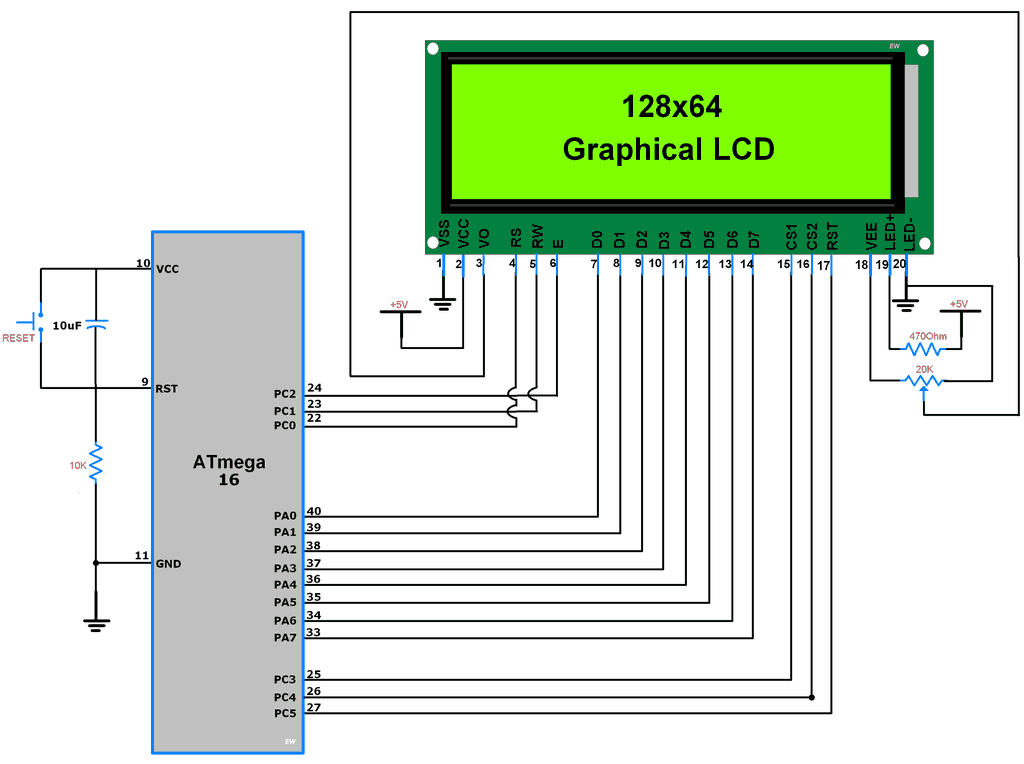
Connection Diagram of GLCD 128x64 with ATmega16/32
Code for Text Print on GLCD using ATmega16/32
/*
* ATmega_GLCD_TextFont
* http://electronicwings.com
*/
#define F_CPU 8000000UL /* Define CPU clock Freq 8MHz */
#include <avr/io.h> /* Include AVR std. library file */
#include <util/delay.h> /* Include delay header file */
#include <stdio.h> /* Include std i/o library file */
#include "Font_Header.h"
#define Data_Port PORTA /* Define data port for GLCD */
#define Command_Port PORTC /* Define command port for GLCD */
#define Data_Port_Dir DDRA /* Define data port for GLCD */
#define Command_Port_Dir DDRC /* Define command port for GLCD */
#define RS PC0 /* Define control pins */
#define RW PC1
#define EN PC2
#define CS1 PC3
#define CS2 PC4
#define RST PC5
#define TotalPage 8
void GLCD_Command(char Command) /* GLCD command function */
{
Data_Port = Command; /* Copy command on data pin */
Command_Port &= ~(1 << RS); /* Make RS LOW for command register*/
Command_Port &= ~(1 << RW); /* Make RW LOW for write operation */
Command_Port |= (1 << EN); /* HIGH-LOW transition on Enable */
_delay_us(5);
Command_Port &= ~(1 << EN);
_delay_us(5);
}
void GLCD_Data(char Data) /* GLCD data function */
{
Data_Port = Data; /* Copy data on data pin */
Command_Port |= (1 << RS); /* Make RS HIGH for data register */
Command_Port &= ~(1 << RW); /* Make RW LOW for write operation */
Command_Port |= (1 << EN); /* HIGH-LOW transition on Enable */
_delay_us(5);
Command_Port &= ~(1 << EN);
_delay_us(5);
}
void GLCD_Init() /* GLCD initialize function */
{
Data_Port_Dir = 0xFF;
Command_Port_Dir = 0xFF;
/* Select both left & right half of display & Keep reset pin high */
Command_Port |= (1 << CS1) | (1 << CS2) | (1 << RST);
_delay_ms(20);
GLCD_Command(0x3E); /* Display OFF */
GLCD_Command(0x40); /* Set Y address (column=0) */
GLCD_Command(0xB8); /* Set x address (page=0) */
GLCD_Command(0xC0); /* Set z address (start line=0) */
GLCD_Command(0x3F); /* Display ON */
}
void GLCD_ClearAll() /* GLCD all display clear function */
{
int i,j;
/* Select both left & right half of display */
Command_Port |= (1 << CS1) | (1 << CS2);
for(i = 0; i < TotalPage; i++)
{
GLCD_Command((0xB8) + i);/* Increment page */
for(j = 0; j < 64; j++)
{
GLCD_Data(0); /* Write zeros to all 64 column */
}
}
GLCD_Command(0x40); /* Set Y address (column=0) */
GLCD_Command(0xB8); /* Set x address (page=0) */
}
void GLCD_String(char page_no, char *str)/* GLCD string write function */
{
unsigned int i, column;
unsigned int Page = ((0xB8) + page_no);
unsigned int Y_address = 0;
float Page_inc = 0.5;
Command_Port |= (1 << CS1); /* Select Left half of display */
Command_Port &= ~(1 << CS2);
GLCD_Command(Page);
for(i = 0; str[i] != 0; i++) /* Print char in string till null */
{
if (Y_address > (1024-(((page_no)*128)+FontWidth)))
break;
if (str[i]!=32)
{
for (column=1; column<=FontWidth; column++)
{
if ((Y_address+column)==(128*((int)(Page_inc+0.5))))
{
if (column == FontWidth)
break;
GLCD_Command(0x40);
Y_address = Y_address + column;
Command_Port ^= (1 << CS1);
Command_Port ^= (1 << CS2);
GLCD_Command(Page + Page_inc);
Page_inc = Page_inc + 0.5;
}
}
}
if (Y_address>(1024-(((page_no)*128)+FontWidth)))
break;
if((font[((str[i]-32)*FontWidth)+4])==0 || str[i]==32)
{
for(column=0; column<FontWidth; column++)
{
GLCD_Data(font[str[i]-32][column]);
if((Y_address+1)%64==0)
{
Command_Port ^= (1 << CS1);
Command_Port ^= (1 << CS2);
GLCD_Command((Page+Page_inc));
Page_inc = Page_inc + 0.5;
}
Y_address++;
}
}
else
{
for(column=0; column<FontWidth; column++)
{
GLCD_Data(font[str[i]-32][column]);
if((Y_address+1)%64==0)
{
Command_Port ^= (1 << CS1);
Command_Port ^= (1 << CS2);
GLCD_Command((Page+Page_inc));
Page_inc = Page_inc + 0.5;
}
Y_address++;
}
GLCD_Data(0);
Y_address++;
if((Y_address)%64 == 0)
{
Command_Port ^= (1 << CS1);
Command_Port ^= (1 << CS2);
GLCD_Command((Page+Page_inc));
Page_inc = Page_inc + 0.5;
}
}
}
GLCD_Command(0x40); /* Set Y address (column=0) */
}
int main(void)
{
GLCD_Init(); /* Initialize GLCD */
GLCD_ClearAll(); /* Clear all GLCD display */
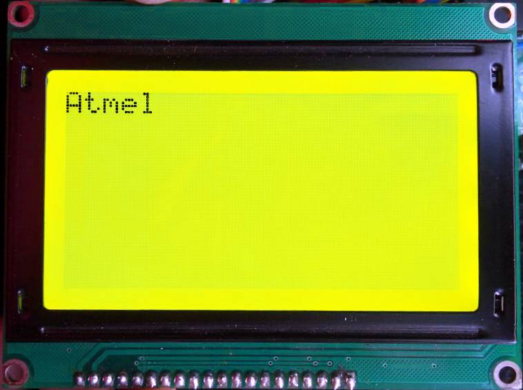
GLCD_String(0,"Atmel"); /* Print String on 0th page of display */
while(1);
}
Output Image
Programming AVR ATmega16 to Display Image on GLCD
We are using the same functions that are used for displaying text except for the GLCD_String function, which is modified here to print image data on GLCD.
- Binary Image is of a total size of 128x64 pixels. So we need an array of 1024 bytes [(128*64)/8=1024 bytes] to store the image in the microcontroller.
- ATmega16 has 1K bytes of RAM and 16K bytes of Program memory, hence we are storing the image array in program memory.
- To store the image array in the program memory of ATmega16 we need to include below header file in Atmel Studio
#include <avr/pgmspace.h>- The above header file consists of functions related to storing and retrieving data from program memory.
- Now we need to use the ‘PROGMEM’ macro to put the image array in program memory
e.g. const char buffer[6] PROGMEM = {0, 1, 2, 3, 4, 5};- Now we can read stored array element by function
Char byte = pgm_read_byte(&(buffer[i]));- Refer Storing & Retrieving Data in the Program Space
- The image array is defined in the Image.h file.
Code for Print Image on GLCD 128x64 using ATmega16/32
/*
 * ATmega_GLCD_Image
 * http://electronicwings.com
 */

#define F_CPU 8000000UL			/* Define CPU clock Frequency 8MHz */
#include <avr/io.h>			/* Include AVR std. library file */
#include <util/delay.h>			/* Include defined delay header file */
#include <stdio.h>			/* Include standard i/o library file */
#include "Image.h"

#define Data_Port		PORTA	/* Define data port for GLCD */
#define Command_Port		PORTC	/* Define command port for GLCD */
#define Data_Port_Dir		DDRA	/* Define data port for GLCD */
#define Command_Port_Dir	DDRC	/* Define command port for GLCD */

#define RS			PC0	/* Define control pins */
#define RW			PC1
#define EN			PC2
#define CS1			PC3
#define CS2			PC4
#define RST			PC5

#define TotalPage		8

void GLCD_Command(char Command)		/* GLCD command function */
{
	Data_Port = Command;		/* Copy command on data pin */
	Command_Port &= ~(1 << RS);	/* Make RS LOW for command register*/
	Command_Port &= ~(1 << RW);	/* Make RW LOW for write operation */
	Command_Port |=  (1 << EN);	/* Make HIGH-LOW transition on Enable */
	_delay_us(5);
	Command_Port &= ~(1 << EN);
	_delay_us(5);
}

void GLCD_Data(char Data)		/* GLCD data function */
{
	Data_Port = Data;		/* Copy data on data pin */
	Command_Port |=  (1 << RS);	/* Make RS HIGH for data register */
	Command_Port &= ~(1 << RW);	/* Make RW LOW for write operation */
	Command_Port |=  (1 << EN);	/* Make HIGH-LOW transition on Enable */
	_delay_us(5);
	Command_Port &= ~(1 << EN);
	_delay_us(5);
}

void GLCD_Init()			/* GLCD initialize function */
{
	Data_Port_Dir = 0xFF;
	Command_Port_Dir = 0xFF;
	/* Select both left & right half of display & Keep reset pin high */
	Command_Port |= (1 << CS1) | (1 << CS2) | (1 << RST);
	_delay_ms(20);
	GLCD_Command(0x3E);		/* Display OFF */
	GLCD_Command(0x40);		/* Set Y address (column=0) */
	GLCD_Command(0xB8);		/* Set x address (page=0) */
	GLCD_Command(0xC0);		/* Set z address (start line=0) */
	GLCD_Command(0x3F);		/* Display ON */
}

void GLCD_ClearAll()			/* GLCD all display clear function */
{
	int i,j;
	/* Select both left & right half of display */
	Command_Port |= (1 << CS1) | (1 << CS2);
	for(i = 0; i < TotalPage; i++)
	{
		GLCD_Command((0xB8) + i);/* Increment page */
		for(j = 0; j < 64; j++)
		{
			GLCD_Data(0);	/* Write zeros to all 64 column */
		}
	}
	GLCD_Command(0x40);		/* Set Y address (column=0) */
	GLCD_Command(0xB8);		/* Set x address (page=0) */
}

void GLCD_String(const char* image)	/* GLCD string write function */
{
	int column,page,page_add=0xB8,k=0;
	float page_inc=0.5;
	char byte;

	Command_Port |= (1 << CS1);	/* Select Left half of display */
	Command_Port &= ~(1 << CS2);

	for(page=0;page<16;page++)	/* Print pages(8 page of each half)*/
	{
		for(column=0;column<64;column++)
		{
			byte = pgm_read_byte(&image[k+column]);
			GLCD_Data(byte);/* Print 64 column of each page */
		}
		Command_Port ^= (1 << CS1);/* Change segment controller */
		Command_Port ^= (1 << CS2);
		GLCD_Command((page_add+page_inc));/* Increment page address*/
		page_inc=page_inc+0.5;
		k=k+64;			/* Increment pointer */
	}
	GLCD_Command(0x40);		/* Set Y address (column=0) */
	GLCD_Command(0xB8);		/* Set x address (page=0) */
}

int main(void)
{
	GLCD_Init();			/* Initialize GLCD */
	GLCD_ClearAll();		/* Clear all GLCD display */
	GLCD_String(img);		/* Print Image Array */
	while(1);
}
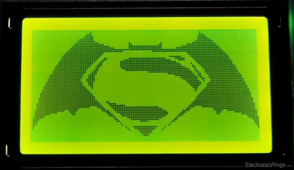
Output Image
Animation on GLCD
To make animation on GLCD 128x64 JHD12864E display do the below steps,
- Take two or more images in a manner that their sequence will create an illusion of motion.
- Convert it to Binary image data using the Image2GLCD application.
- And print them on GLCD in a series of sequences. It will create animation.
- Note that provides a sufficient delay in between images.
Video of Image Display on GLCD using ATmega16/32
Components Used |
||
|---|---|---|
| GLCD 128x64 GLCD 128x64 is a Graphical LCD having 128x64 pixel resolution. It is used to display values, text with different fonts, binary images, animation, custom character. |
X 1 | |
| ATmega 16 ATmega 16 |
X 1 | |
| Atmega32 Atmega32 |
X 1 | |