Introduction to I2C
I2C (Inter-Integrated Circuit) is a serial bus interface connection protocol. It is also called TWI (two-wire interface) since it uses only two wires for communication, that two wires called SDA (serial data) and SCL (serial clock). AVR-based ATmega16/ATmega32 has a TWI module made up of several submodules as shown in the figure.
I2C works in two modes namely,
- Master mode
- Slave mode
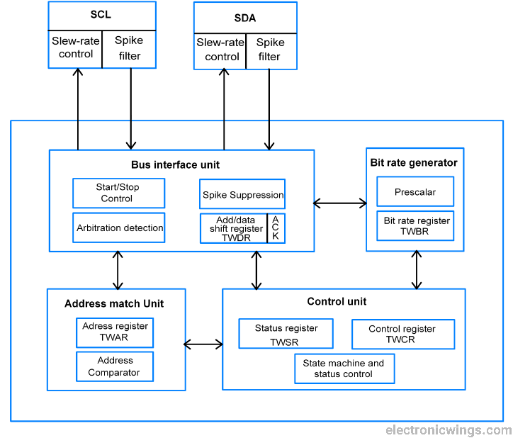
SDA & SCL pins
- These pins are used to interface the TWI based external peripherals and microcontroller.
- The output drivers contain a slew-rate limiter. The input stages contain a spike suppression unit which removes spikes shorter than 50 ns.
Bus interface unit
- The bus interface unit contains Start/Stop control which is responsible for the generation and detection of START, REPEATED START, and STOP conditions.
- TWDR add/data shift register contain data to be transmitted and received.
- ACK bit receives ack/nack in transmitter mode and it is generated through software in receiving mode.
- The Spike suppression unit takes care of spikes whereas arbitration detection continuously monitors bus status and informs the control unit about it.
Address match unit
In slave mode, the Address match unit receives an incoming 7-bit address and compares with the address in TWAR (Two Wire Address Register) register to check whether it matches or not and upon match occur it intimate to control unit to take necessary action. It also considers the general call address if the TWGCE bit in TWAR is enabled.
Bit rate generator unit
The bit rate generator unit controls the SCL period in the master mode to generate SCL frequency. It is calculated by,
SCL frequency = (CPU CLK frequency)/(16+2(TWBR)*4^TWPS )
Where TWPS is a value of a pre-scaler bit in TWSR.
Control unit
- The Control unit contains TWSR (TWI status register), TWCR (TWI control register).
- It controls the overall process of attention for necessary events, identifying events when occur, TWINT interrupts assertion, and update TWSR.
- As long as the TWINT flag set SCL held low. TWINT set whenever TWI completes the current task.
Let see registers in the ATmega16/32 I2C module
TWBR: TWI Bit Rate Register
TWI bit rate register used in generating SCL frequency while operating in master mode

TWCR: TWI Control Register
TWI control resistor used to control events of all I2C communication.

Bit 7 – TWINT: TWI interrupt
- This bit gets set whenever TWI completes its current event (like start, stop, transmit, receive, etc).
- While I-bit in SREG and TWIE bit in TWCR is enabled then TWI interrupt vector called whenever TWI interrupt occur.
- TWI interrupt flag must be cleared by software by writing a logical one to it. This bit is not automatically cleared by hardware.
Bit 6 – TWEA: TWI enable acknowledgment bit
- This is TWI acknowledgment enable bit, it is set in receiver mode to generate acknowledgment and cleared in transmit mode.
Bit 5 – TWSTA: TWI START condition bit
- The master device set this bit to generate START condition by monitoring free bus status to take control over the TWI bus.
Bit 4 – TWSTO: TWI STOP condition bit
- The master device set this bit to generate STOP condition to leave control over the TWI bus.
Bit 3 – TWWC: TWI write collision
- This bit gets set when writing to the TWDR register before the current transmission not complete i.e. TWINT is low.
Bit 2 – TWEN: TWI enable bit
- This bit set to enables the TWI interface in the device and takes control over the I/O pins.
Bit 1 - Reserved
Bit 0 – TWIE: TWI interrupt enable
- This bit is used to enable TWI to interrupt routine while the I-bit of SREG is set as long as the TWINT flag is high.
TWSR: TWI Status Register

Bit 7:Bit 3 - TWS7: TWS3: TWI status bits
- TWI status bits shows the status of TWI control and bus
Bit 1:0 - TWPS1:TWPS0: TWI pre-scaler bits
- TWI pre-scaler bits used in bit rate formula to calculate SCL frequency
| TWPS1 | TWPS0 | Exponent | Pre-scaler value |
|---|---|---|---|
| 0 | 0 | 0 | 1 |
| 0 | 1 | 1 | 4 |
| 1 | 0 | 2 | 16 |
| 1 | 1 | 3 | 64 |
TWDR: TWI Data Register
- TWDR contains data to be transmitted or received.
- It’s not writable while TWI is in process of shifting a byte.
- The data remains stable as long as TWINT is set.

TWAR: TWI Address Register
- TWAR register contains the address of the TWI unit in slave mode.
- It is mostly used in the multi-master system.

Bit 7:1 - TWA6: TWA0: TWI address bits
- TWI address bits contain TWI 7-bit address with which it can called by other masters in slave mode.
Bit 0 – TWGCE: TWI general call enable bit
- TWI general call enable bit when set it enables recognition of general call over the TWI bus
There are four transmission modes in I2C in which the I2C device works.
- When the device is Master it works in MT and MR transmission modes.
- And when the device is Slave it works in ST and SR transmission modes.
| SR No. | Transmission mode | Operation |
|---|---|---|
| 1 | Master Transmitter (MT) | Master device writes data to SDA. |
| 2 | Master Receiver (MR) | Master device read data from SDA. |
| 3 | Slave Transmitter (ST) | Slave device writes data to SDA. |
| 4 | Slave Receiver (SR) | Slave device read data from SDA. |
Let see how to program I2C in Master and Slave mode.
Programming ATmega16 I2C in Master mode
To program AVR ATmega16 I2C in master mode first need to initialize the I2C module with SCL frequency and then need to perform read and write operation using START, REPEATED START, STOP events. Let first initialize the TWI module in ATmega16.
I2C Initialization
Here to initializeATmega16 TWI in the master mode, we need to set SCL clock frequency by setting values in the TWBR register and TWPS bits in the TWSR register.
TWBR value is defined by the above SCL frequency formula. e.g.
/* Define bit rate */
#define BITRATE(TWSR)	((F_CPU/SCL_CLK)-16)/(2*pow(4,(TWSR&((1<<TWPS0)|(1<<TWPS1)))))
Now load this value in the TWBR register
void I2C_Init()			/* I2C initialize function */
{
    TWBR = BITRATE(TWSR=0x00);	/* Get bit rate register value by formula */
}
Now let see I2C events
I2C Events
As AVR I2C is byte-oriented and interrupt based i.e. interrupts issued after every bus event completion. Events like Start, Write, Read, Stop. Also status gets updated after every bus event. So let’s see about I2C events and conditions with their function codes.
I2C Events in Master mode
START (S)
- START condition issued by master.
- It is generated by High to Low transition on SDA while SCL is High.
- While the bus is a free to master device issue the START condition with the slave device address (SLA) to initiate transmission.
I2C_Start function
This function initiate the START condition
Input argument: - it has the input argument of slave device write address (SLA+W).
Return: - it returns the status of the event.
uint8_t I2C_Start(charwrite_address)/* I2C start function */
{
    uint8_t status;		/* Declare variable */
    TWCR=(1<<TWSTA)|(1<<TWEN)|(1<<TWINT); /* Enable TWI, generate START */
    while(!(TWCR&(1<<TWINT)));	/* Wait until TWI finish its current job */
    status=TWSR&0xF8;		/* Read TWI status register */
    if(status!=0x08)		/* Check weather START transmitted or not? */
    return 0;			/* Return 0 to indicate start condition fail */
    TWDR=write_address;		/* Write SLA+W in TWI data register */
    TWCR=(1<<TWEN)|(1<<TWINT);	/* Enable TWI & clear interrupt flag */
    while(!(TWCR&(1<<TWINT)));	/* Wait until TWI finish its current job */
    status=TWSR&0xF8;		/* Read TWI status register */
    if(status==0x18)		/* Check for SLA+W transmitted &ack received */
    return 1;			/* Return 1 to indicate ack received */
    if(status==0x20)		/* Check for SLA+W transmitted &nack received */
    return 2;			/* Return 2 to indicate nack received */
    else
    return3;			/* Else return 3 to indicate SLA+W failed */
}
REPEATED START (Sr)
- REPEATED START condition issued by the master.
- It is generated by issuing another one START condition to initiate a new transmission.
- REPEATED START condition with slave device address (SLA) is issued in between START and STOP condition
I2C_Repeated_Start function
This function generates REPEATED START condition for reading operation.
Input argument: - it has the input argument of slave device read address (SLA+R).
Return: - it returns the status of the event.
uint8_t I2C_Repeated_Start(charread_address) /* I2C repeated start function */
{
    uint8_t status;		/* Declare variable */
    TWCR=(1<<TWSTA)|(1<<TWEN)|(1<<TWINT);/* Enable TWI, generate start */
    while(!(TWCR&(1<<TWINT)));	/* Wait until TWI finish its current job */
    status=TWSR&0xF8;		/* Read TWI status register */
    if(status!=0x10)		/* Check for repeated start transmitted */
    return 0;			/* Return 0 for repeated start condition fail */
    TWDR=read_address;		/* Write SLA+R in TWI data register */
    TWCR=(1<<TWEN)|(1<<TWINT);	/* Enable TWI and clear interrupt flag */
    while(!(TWCR&(1<<TWINT)));	/* Wait until TWI finish its current job */
    status=TWSR&0xF8;		/* Read TWI status register */
    if(status==0x40)		/* Check for SLA+R transmitted &ack received */
    return 1;			/* Return 1 to indicate ack received */
    if(status==0x48)		/* Check for SLA+R transmitted &nack received */
    return 2;			/* Return 2 to indicate nack received */
    else
    return 3;			/* Else return 3 to indicate SLA+W failed */
}
WRITE (W)
- WRITE data/address event is issued by the master after successful acknowledgment of START received from the slave device.
I2C_Write function
This function writes data/address on the bus
Input argument: - it has an input argument of data/address.
Return: - it returns the status of the event.
uint8_t I2C_Write(chardata)	/* I2C write function */
{
    uint8_tstatus;		/* Declare variable */
    TWDR=data;			/* Copy data in TWI data register */
    TWCR=(1<<TWEN)|(1<<TWINT);	/* Enable TWI and clear interrupt flag */
    while(!(TWCR&(1<<TWINT)));	/* Wait until TWI finish its current job */
    status=TWSR&0xF8;		/* Read TWI status register */
    if(status==0x28)		/* Check for data transmitted &ack received */
    return 0;			/* Return 0 to indicate ack received */
    if(status==0x30)		/* Check for data transmitted &nack received */
    return 1;			/* Return 1 to indicate nack received */
    else
    return 2;			/* Else return 2 for data transmission failure */
}
READ (R)
- Read data event is issued by the master after successful REPEATED START condition.
I2C_Read_Ack function
This function read data available on the SDA line and returns its acknowledgment to the slave device about data read successful and also tells slave to transmit another data.
Input argument: - it has no input argument.
Return : - it returnsreceived data.
char I2C_Read_Ack()		/* I2C read ack function */
{
    TWCR=(1<<TWEN)|(1<<TWINT)|(1<<TWEA); /* Enable TWI, generation of ack */
    while(!(TWCR&(1<<TWINT)));	/* Wait until TWI finish its current job */
    returnTWDR;			/* Return received data */
}
I2C_Read_Nack function
This function read last needed data byte available on the SDA line but does not returns an acknowledgment of it. It used to indicate slave that master don’t want next data and want to stop communication.
Input argument : - it has no input argument.
Return : - it returns received data.
char I2C_Read_Nack()		/* I2C read nack function */
{
    TWCR=(1<<TWEN)|(1<<TWINT);	/* Enable TWI and clear interrupt flag */
    while(!(TWCR&(1<<TWINT)));	/* Wait until TWI finish its current job */
    return TWDR;		/* Return received data */
}
STOP (P)
- STOP event issued by the master to indicate it has to stop.
- It is generated by Low to High transition on SDA while SCL is High.
I2C_Stop function
This function initiates the STOP condition
Input argument: - it has no input argument.
Return: - it does not return any data type.
void I2C_Stop()			/* I2C stop function */
{
    TWCR=(1<<TWSTO)|(1<<TWINT)|(1<<TWEN);/* Enable TWI, generate stop */
    while(TWCR&(1<<TWSTO));	/* Wait until stop condition execution */
}
Example
Let’s take example for first Master Transmitter (MT)and Master Receiver (MR) mode. Consider ATmega16 as Master and EEPROM memory as Slave, we can write data to EEPROM in Master Transmitter (MT) mode and read the same from EEPROM in Master Receiver (MR) mode.
- Here ATmega16 is the master device and EEPROM is a slave device
Programming steps for Write operation:
- Initialize I2C.
- Generate START condition.
- Send the Slave device to write address (SLA+W) and check for acknowledgment.
- Write memory location addresses for memory devices to which we want to write.
- Write data till the last byte.
- Generate a STOP condition.
Programming steps for reading operation:
- Initialize I2C.
- Generate START condition.
- Write device Write address (SLA+W) and check for acknowledgment.
- Write a memory location address for memory devices.
- Generate REPEATED START condition.
- Read data and return acknowledgment.
- Return Not acknowledgment for the last byte.
- Generate a STOP condition.
ATmega16/32 I2C Master Program
/*
 * ATmega16_Master_I2C.c
 * http://www.electronicwings.com
 */


#define F_CPU 8000000UL		/* Define CPU clock Frequency 8MHz */
#include <avr/io.h>		/* Include AVR std. library file */
#include <util/delay.h>		/* Include Delay header file */
#include <string.h>		/* Include string header file */
#include "I2C_Master_H_file.h"	/* Include I2C header file */
#include "LCD_16x2_H_file.h"	/* Include LCD header file */

#define EEPROM_Write_Addess		0xA0
#define EEPROM_Read_Addess		0xA1

int main(void)
{
    char array[10] = "test";	/* Declare array to be print */
    LCD_Init();			/* Initialize LCD */
    I2C_Init();			/* Initialize I2C */
    I2C_Start(EEPROM_Write_Addess);/* Start I2C with device write address */
    I2C_Write(0x00);		/* Write start memory address for data write */
    for (int i = 0; i<strlen(array); i++)/* Write array data */
	{
		I2C_Write(array[i]);
	}
    I2C_Stop();			/* Stop I2C */
    _delay_ms(10);
    I2C_Start(EEPROM_Write_Addess);/* Start I2C with device write address */
    I2C_Write(0x00);		/* Write start memory address */
    I2C_Repeated_Start(EEPROM_Read_Addess);/* Repeat start I2C SLA+R */
    for (int i = 0; i<strlen(array); i++)/* Read data with acknowledgment */
	{
		LCD_Char(I2C_Read_Ack());
	}
    I2C_Read_Nack();		/* Read flush data with nack */
    I2C_Stop();			/* Stop I2C */
    return 0;
}
Programming ATmega16 I2C in Slave Mode
To program AVR basedATmega16 I2C in slave mode we need to initialize TWI module. In slave mode device can not generate START, REPEATED START or STOP condition. A slave device need to always listen to the TWI bus to be get addressed by any Master device or general call. Let initialize the TWI module in slave mode.
I2C Slave initialization function
Here to initialize ATmega16 in slave mode we need to assign a 7-bit device address in the TWAR register. After assigning the address, we need to enable TWI and acknowledgment bit in TWCR. And clear TWI interrupts the flag by writing logic 1 to it.
Input argument: - it has an input argument of the slave address.
Return: - it does not return any data type.
void I2C_Slave_Init(uint8_tslave_address)
{
    TWAR=slave_address;		/* Assign Address in TWI address register */
    TWCR=(1<<TWEN)|(1<<TWEA)|(1<<TWINT);/* Enable TWI, Enable ack generation */
}
Now let see events occurred in slave mode,
Listen to bus
- The slave device always needs to listen to the TWI bus to check whether it gets addressed by any Master.
- When it is addressed, TWINT bit get set. So need to monitor TWINT bit.
I2C_Slave_Listen function
Input argument : - it has no any input argument.
Return : - it returns event status.
int8_t I2C_Slave_Listen()
{
    while(1)
     {
	uint8_t status;			/* Declare variable */
	while(!(TWCR&(1<<TWINT)));	/* Wait to be addressed */
	status=TWSR&0xF8;		/* Read TWI status register */
	if(status==0x60||status==0x68)	/* Own SLA+W received &ack returned */
	return 0;			/* Return 0 to indicate ack returned */
	if(status==0xA8||status==0xB0)	/* Own SLA+R received &ack returned */
	return 1;			/* Return 0 to indicate ack returned */
	if(status==0x70||status==0x78)	/* General call received &ack returned */
	return 2;			/* Return 1 to indicate ack returned */
	else
	continue;			/* Else continue */
     }
}
Transmit data
- After getting addressed by the master with the SLA+R address, then the slave must send the requested data.
- Data to be sent need to write in the TWDR register.
- After data write, enable TWI with acknowledgment and clear interrupt flag.
- If acknowledgement not received frommaster,then slave device will clear TWINT flag and again listen to bus.
- Also if REPEATED START/STOP received,then slave device will clear TWINT flag and again listen to bus.
I2C_Slave_Transmit function
Input argument: - it has an input argument of character data to be sent.
Return : - it returns event status.
int8_t I2C_Slave_Transmit(chardata)
{
    uint8_t status;
    TWDR=data;			/* Write data to TWDR to be transmitted */
    TWCR=(1<<TWEN)|(1<<TWINT)|(1<<TWEA);/* Enable TWI & clear interrupt flag */
    while(!(TWCR&(1<<TWINT)));	/* Wait until TWI finish its current job */
    status=TWSR&0xF8;		/* Read TWI status register */
    if(status==0xA0)		/* Check for STOP/REPEATED START received */
     {
	TWCR|=(1<<TWINT);	/* Clear interrupt flag & return -1 */
	return -1;
     }
    if(status==0xB8)		/* Check for data transmitted &ack received */
    return0;			/* If yes then return 0 */
    if(status==0xC0)		/* Check for data transmitted &nack received */
     {
	TWCR|=(1<<TWINT);	/* Clear interrupt flag & return -2 */
	return -2;
     }
    if(status==0xC8)		/* Last byte transmitted with ack received */
    return -3;			/* If yes then return -3 */
    else			/* else return -4 */
    return -4;
}
Receive data
- After getting addressed by the master with the SLA+W address, then the slave needs to receive data sent by the master.
- After each byte received, slaves need to return acknowledge about it to the master.
- If REPEATED START/STOP received, then the slave device will clear the TWINT flag and again listen to the bus.
I2C_Slave_Recieve function
Input argument : - it has no input argument.
Return: - it returns received data or event status.
char I2C_Slave_Receive()
{
    uint8_tstatus;		/* Declare variable */
    TWCR=(1<<TWEN)|(1<<TWEA)|(1<<TWINT);/* Enable TWI & generation of ack */
    while(!(TWCR&(1<<TWINT)));	/* Wait until TWI finish its current job */
    status=TWSR&0xF8;		/* Read TWI status register */
    if(status==0x80||status==0x90)/* Check for data received &ack returned */
    return TWDR;		/* If yes then return received data */

/* Check for data received, nack returned & switched to not addressed slave mode */
    if(status==0x88||status==0x98)
    return TWDR;		/* If yes then return received data */
    if(status==0xA0)		/* Check wether STOP/REPEATED START */
     {
	TWCR|=(1<<TWINT);	/* Clear interrupt flag & return -1 */
	return -1;
     }
    else
    return -2;			/* Else return -2 */
}
Example
Let take an example, here ATmega16 will act as the Master device, and ATmega32 act as a Slave device. First Master device will send count to Slave device and then same master will read from slave device.
Atmega16/32 I2C Interfacing Diagram
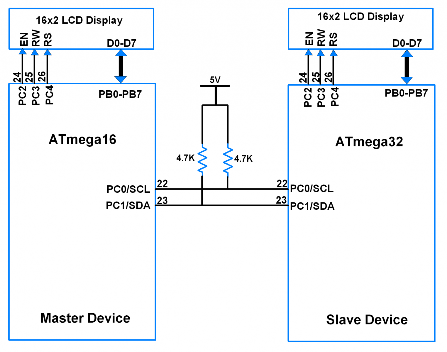
Programming steps in the master device
- Initialize I2C.
- Generate START condition.
- Write device Write address (SLA+W) and check for acknowledgement.
- After acknowledgement write data to slave device.
- Generate REPEATED START condition with SLA+R.
- Receive data from slave device.
Programming steps in slave device
- Initialize I2C with slave device address.
- Listen to bus for get addressed by master.
- While addressed with SLA+W by master device, receive data from master device.
- Return acknowledgement after each byte received.
- Clear interrupt flag after REPEATED START/STOP received.
- Print received data on LCD.
- Again listen to bus for get addressed by master.
- While addressed with SLA+R by master device, transmit data to master device.
- Transmit data till NACK/REPEATED START/STOP receive from master.
- Clear interrupt flag after NACK/REPEATED START/STOP received.
ATmega16/32 I2C master program
/*
 * ATmega16_Master.c
 * http://www.electronicwings.com
 *
 */

#define F_CPU 8000000UL		/* Define CPU clock Frequency 8MHz */
#include <avr/io.h>		/* Include AVR std. library file */
#include <util/delay.h>		/* Include inbuilt defined Delay header file */
#include <stdio.h>		/* Include standard I/O header file */
#include <string.h>		/* Include string header file */
#include "I2C_Master_H_file.h"	/* Include I2C header file */
#include "LCD_16x2_H_file.h"	/* Include LCD header file */

#define Slave_Write_Address		0x20
#define Slave_Read_Address		0x21
#define	count				10

int main()
{
    char buffer[10];

    LCD_Init();			/* Initialize LCD */
    I2C_Init();			/* Initialize I2C */

    LCD_String_xy(1, 0, "Master Device");

    while (1)
     {
	LCD_String_xy(2, 0, "Sending :       ");
	I2C_Start_Wait(Slave_Write_Address);/* Start I2C with SLA+W */
	_delay_ms(5);
	for (uint8_t i = 0; i < count ; i++)
	 {
	    sprintf(buffer, "%d    ",i);
	    LCD_String_xy(2, 13, buffer);
	    I2C_Write(i);	/* Send Incrementing count */
	    _delay_ms(500);
	 }
	LCD_String_xy(2, 0, "Receiving :       ");
	I2C_Repeated_Start(Slave_Read_Address);/* Repeated Start with SLA+R */
	_delay_ms(5);
	for (uint8_t i = 0; i < count; i++)
	 {
	    if(i < count - 1)
	    sprintf(buffer, "%d    ", I2C_Read_Ack());/* Read & Ack of data */
	    else
	    sprintf(buffer, "%d    ", I2C_Read_Nack());/* Read & Nack to data */
	    LCD_String_xy(2, 13, buffer);
	    _delay_ms(500);
	 }
	I2C_Stop();		/* Stop I2C */
     }
}
ATmega16/32 I2C slave program
/*
 * ATmega32_Slave.c
 * http://www.electronicwings.com
 *
 */


#define F_CPU 8000000UL		/* Define CPU clock Frequency 8MHz */
#include <avr/io.h>			/* Include AVR std. library file */
#include <util/delay.h>		/* Include inbuilt defined Delay header file */
#include <stdio.h>			/* Include standard I/O header file */
#include <string.h>			/* Include string header file */
#include "LCD_16x2_H_file.h"	/* Include LCD header file */
#include "I2C_Slave_H_File.h"	/* Include I2C slave header file */

#define Slave_Address		0x20

int main(void)
{
    char buffer[10];
    int8_t count = 0;

    LCD_Init();
    I2C_Slave_Init(Slave_Address);

    LCD_String_xy(1, 0, "Slave Device");

    while (1)
     {
	switch(I2C_Slave_Listen())				/* Check for SLA+W or SLA+R */
	 {
	    case 0:
		{
		  LCD_String_xy(2, 0, "Receiving :       ");
		  do
		  {
		    sprintf(buffer, "%d    ", count);
		    LCD_String_xy(2, 13, buffer);
		    count = I2C_Slave_Receive();	/* Receive data byte*/
		  } while (count != -1);			/* Receive until STOP/REPEATED START */
		  count = 0;
		  break;
		}
	    case 1:
		{
		  int8_t Ack_status;
		  LCD_String_xy(2, 0, "Sending :       ");
		  do
		  {
		    Ack_status = I2C_Slave_Transmit(count);/* Send data byte */
		    sprintf(buffer, "%d    ",count);
		    LCD_String_xy(2, 13, buffer);
		    count++;
		  } while (Ack_status == 0);				/* Send until Ack is receive */
		  break;
		}
	    default:
		break;
	 }
     }
}
Video
Components Used |
||
|---|---|---|
| ATmega 16 ATmega 16 |
X 2 | |
| Atmega32 Atmega32 |
X 2 | |
| Breadboard Breadboard |
X 1 | |
| LCD16x2 Display LCD16x2 Display |
X 2 | |