Overview of DC Motor
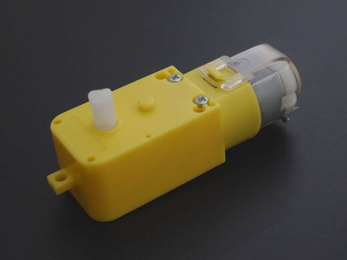
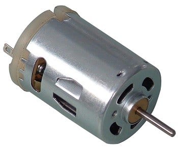
DC motor converts electrical energy in the form of Direct Current into mechanical energy.
In the case of the motor, the mechanical energy produced is in the form of a rotational movement of the motor shaft.
The direction of rotation of the shaft of the motor can be reversed by reversing the direction of Direct Current through the motor.
The motor can be rotated at a certain speed by applying a fixed voltage to it. If the voltage varies, the speed of the motor varies.
Thus, the DC motor speed can be controlled by applying varying DC voltage; whereas the direction of rotation of the motor can be changed by reversing the direction of current through it.
For applying varying voltage, we can make use of the PWM technique.
For reversing the current, we can make use of an H-Bridge circuit or motor driver ICs that employ the H-Bridge technique or other mechanisms.
For more information about DC motors and how to use them, H-Bridge circuit configuration, PWM technique, refers to the topic DC Motors in the sensors and modules section.
For information about PWM in ATmega16 and how to use it, refer to the topic PWM in AVR ATmega16/ATmega32 in the ATmega inside section.
Here we will be using the ADC feature of AVR ATmega16.
For information about ADC in ATmega16 and how to use it, refer to the topic ADC in ATmega16/ATmega32 in the ATmega inside section.
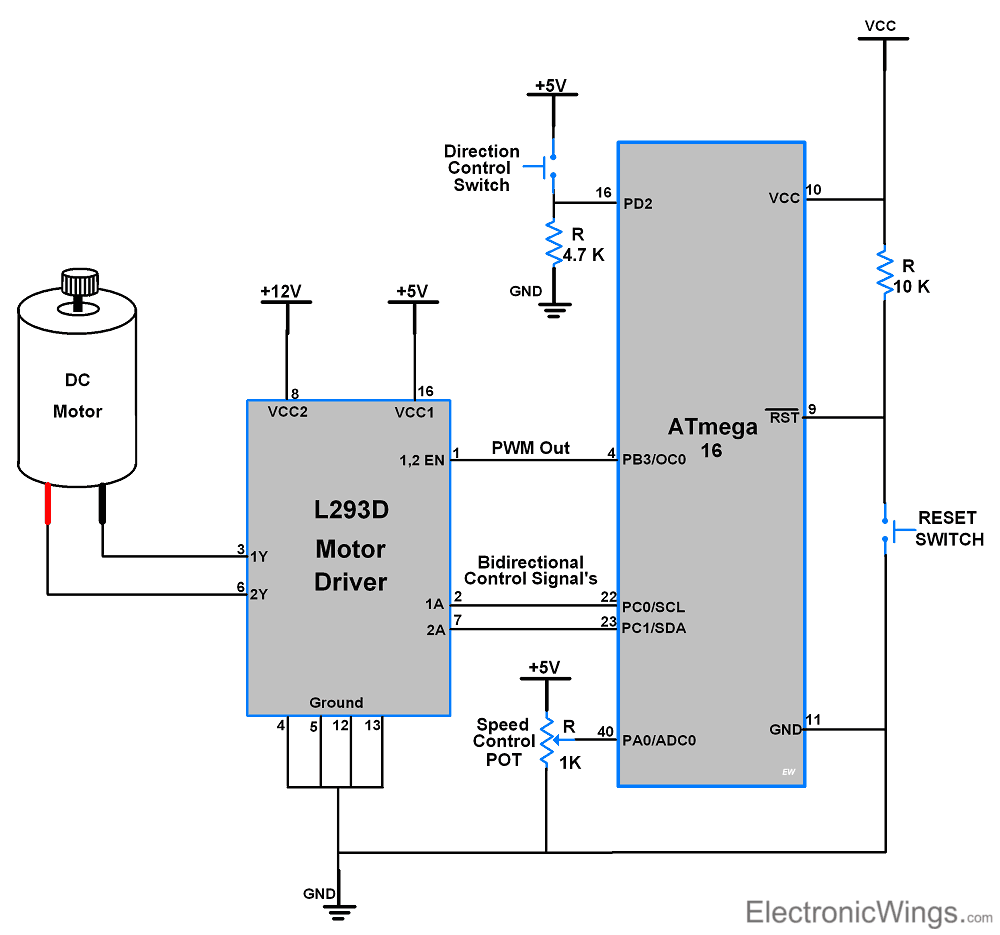
Connection Diagram of DC Motor with ATmega16/32
Speed Control of DC Motor using ATmega16/32
Here, we are going to interface the DC motor with AVR ATmega16 microcontroller. Which we will control the DC motor speed by using POT connected to ADC of ATmega16 and direction by using a switch.
We are going to use the L293D motor driver IC to control the DC motor movement in both directions. It has an in-built H-bridge motor drive.
- As shown in the above figure we have connected the 1kΩ Potentiometer at ADC channel 0 of ATmega16 to change the speed of the DC motor.
- One toggle switch is connected to the INT0 pin (2nd pin of PORTD) which controls the motor rotating direction.
- PORTC is used as an output control signal port. It provides control to motor1 input pins of the L293D motor driver which rotates the motor clockwise and anticlockwise by changing their terminal polarity.
DC Motor Programming steps
- Enable ADC and map its output into 0-255 range.
- Enable Global interrupt, and INT0 external interrupt with the rising edge-triggered mode.
- Set Fast PWM mode of Timer0 with FOSC/64 timer clock.
- ADC value is given to the OCR0 register and in an interrupt routine, we are toggling motor direction.
- Now continuously check for the interrupt for direction and read ADC value for speed control.
- A switch will produce an interrupt which causes to change in motor direction. By varying potentiometer, variable ADC values can be given to OCR0 register to achieve speed variation.
DC Motor Code for ATmega16/32
/*
 * ATmega16 DC Motor control
 * http://www.electronicwings.com
 */

#define F_CPU 8000000UL			/* Define CPU Frequency 8MHz */
#include <avr/io.h>			/* Include AVR std. library file */
#include <avr/interrupt.h>
#include <stdio.h>			/* Include std. library file */
#include <util/delay.h>			/* Include Delay header file */

volatile uint8_t Direction = 0;

void ADC_Init()				/* ADC Initialization function */
{
	DDRA = 0x00;			/* Make ADC port as input */
	ADCSRA = 0x87;			/* Enable ADC, with freq/128 */
	ADMUX = 0x40;			/* Vref: Avcc, ADC channel: 0 */
}

int ADC_Read(char channel)		/* ADC Read function */
{
	ADMUX = 0x40 | (channel & 0x07);/* set input channel to read */
	ADCSRA |= (1<<ADSC);		/* Start ADC conversion */
	while (!(ADCSRA & (1<<ADIF)));	/* Wait until end of conversion */
	ADCSRA |= (1<<ADIF);		/* Clear interrupt flag */
	_delay_ms(1);			/* Wait a little bit */
	return ADCW;			/* Return ADC word */
}

ISR(INT0_vect)
{
	Direction = ~Direction;		/* Toggle Direction */
	_delay_ms(50);			/* Software de-bouncing control delay */
}

int main(void)
{
	DDRC = 0xFF;			/* Make PORTC as output Port */
	DDRD &= ~(1<<PD2);		/* Make INT0 pin as Input */
	DDRB |= (1<<PB3);		/* Make OC0 pin as Output */
	GICR = (1<<INT0);		/* Enable INT0*/
	MCUCR = ((1<<ISC00)|(1<<ISC01));/* Trigger INT0 on Rising Edge triggered */
	sei();				/* Enable Global Interrupt */
	ADC_Init();			/* Initialize ADC */
	TCNT0 = 0;			/* Set timer0 count zero */
	TCCR0 = (1<<WGM00)|(1<<WGM01)|(1<<COM01)|(1<<CS00)|(1<<CS01);/* Set Fast PWM with Fosc/64 Timer0 clock */
	while(1)
	{
		if (Direction !=0)	/* Rotate DC motor Clockwise */
			PORTC = 1;
		else			/* Else rotate DC motor Anticlockwise */
			PORTC = 2;
		OCR0 = (ADC_Read(0)/4);	/* Read ADC and map it into 0-255 to write in OCR0 register */
	}
}
Components Used |
||
|---|---|---|
| ATmega 16 ATmega 16 |
X 1 | |
| Atmega32 Atmega32 |
X 1 | |
| L293D Driver L293D Driver |
X 1 | |
| Mini Push Button Switch - 5-6mm Mini Push Button Switch - 5-6mm |
X 1 | |