Introduction
Generally, compare mode is used for generating periodic events or for generating waveforms.
In compare mode, there is one compare register, where we can set the value to compare with the Timer/counter register value. Once the compare value matches with the timer/counter register value, a compare match occurs. This compare match event can be used for waveform generation.
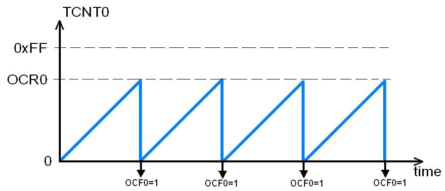
In ATmega 16 / 32, the Timer counts up until the value of the TCNT0 (Timer/counter register) register becomes equal to the content of OCR0 (Compare register). As soon as TCNT0 becomes equal to the OCR0, a compare match occurs, and then the timer will get cleared and the OCF0 flag will get set.
OCF0 flag is located in the TIFR register.
Waveform Generation
Using Normal mode & CTC mode:
TCCR0: Timer / counter control register

Bit 7 - FOC0: Force compare match
After setting this bit, the timer forced to match occur. i.e. setting output compare flag.
Bit 6, 3- WGM00, WGM01- Timer0 mode selection bit
| WGM00 | WGM01 | Timer0 mode selection bit |
|---|---|---|
| 0 | 0 | Normal |
| 0 | 1 | CTC (Clear timer on Compare Match) |
| 1 | 0 | PWM, Phase correct |
| 1 | 1 | Fast PWM |
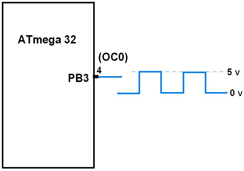
So, we can generate a square wave with PWM waveforms on pin OC0 (output compare pin) using different modes.
Bit 5, 4- COM01:00 (compare output mode)
COM01:00 controls OC0 pin behavior, however, the DDR bit of corresponding OC0 pin must be set to make OC0 pin as an output.
The following table defines the behavior of OC0 pin for the Normal and CTC mode (i.e. WGM00: WGM01= 00 & 01)
| COM01 | COM00 | Description |
|---|---|---|
| 0 | 0 | The normal port operation, OC0 disconnected. |
| 0 | 1 | Toggle OC0 on compare match |
| 1 | 0 | Clear OC0 on compare match |
| 1 | 1 | Set OC0 on compare match |
Bit 2:0 - CS02:CS00: Clock Source Select
These bits are used to select a clock source. When CS02: CS00 = 000, then timer is stopped. As it gets a value between 001 to 101, it gets a clock source and starts as the timer.
| CS02 | CS01 | CS00 | Description |
|---|---|---|---|
| 0 | 0 | 0 | No clock source (Timer / Counter stopped) |
| 0 | 0 | 1 | clk (no pre-scaling) |
| 0 | 1 | 0 | clk / 8 |
| 0 | 1 | 1 | clk / 64 |
| 1 | 0 | 0 | clk / 256 |
| 1 | 0 | 1 | clk / 1024 |
| 1 | 1 | 0 | External clock source on T0 pin. Clock on falling edge |
| 1 | 1 | 1 | External clock source on T0 pin. Clock on rising edge. |
Generating square wave
- Square wave using the normal mode:
To generate a square wave in normal mode, we can set COM bit as toggle mode (COM01:00=01), so OC0 pin will be toggle on each compare match and the square wave will be generated.
Normal Mode Waveform Generation Program
/*
 *  ATmega16 normal mode waveform generation
 *  http://www.electronicwings.com
 */
#include "avr/io.h"
int main ( )
{
	DDRB = DDRB|(1<<3);
	TCCR0 = 0x11;	/* normal mode, clk- no pre-scaling */
	OCR0 = 100;	/* compare value */
	while (1);
	return 0;
}
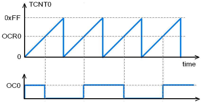
Waveform Generation Using Normal Mode
In normal mode, when a match occurs, the OC0 pin toggles and the timer continues to count up until it reaches to the top value.
Frequency of square wave:
Assuming Fosc=8MHz waveform, T=0.125 μs.
Time period of square wave: 2 x 256 x 0.125 μs = 64 μs
Frequency of wave= 1/64 μs = 15,625 kHz.
2. Square wave Using CTC mode:
This is a better mode than the normal mode for generating square waves because the frequency of the wave can be easily adjusted using the OCR0 register. See the figure
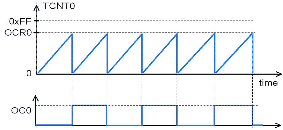
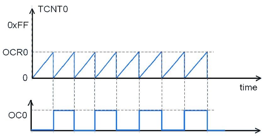
As you can see, when a compare match occurs, the timer value becomes zero.
/*
 *  ATmega16 CTC mode waveform
 *  http://www.electronicwings.com
 */

#include "avr/io.h"
int main ( )
{
	DDRB = DDRB|(1<<3);	/* PB3 (OC0) as output */
	TCCR0 = 0x19;		/* CTC mode, toggle on compare match,
                      		clk- no pre-scaling */
	OCR0 = 200;  		/* compare value */
	while (1);
}
Square wave frequency calculations:
Assuming Fosc=8MHz waveform, T=0.125 μs.
Time period of square wave: 2 x (OCR0+1) x 0.125 μs
= 2 x 201 x 0.125 μs =50.25 μs
Frequency of square wave = 1/50.25 μs = 19.9 KHz.
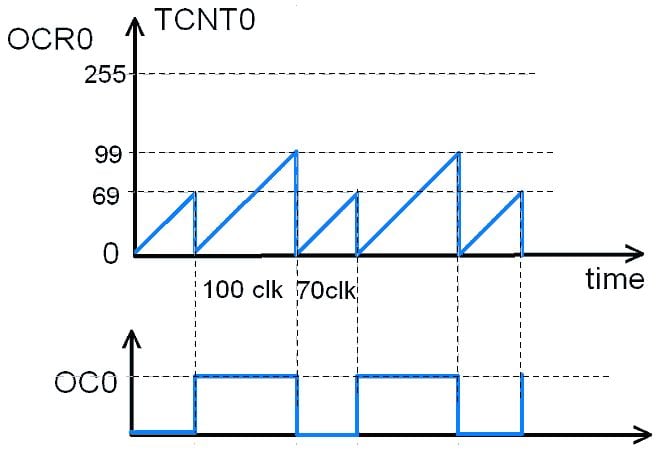
Here we have changed the value of OCR0 in runtime, to generate different pulses in the below program.
/*
 *  ATmega pulses of different time periods
 *  http://www.electronicwings.com
 */

#include "avr/io.h"
int main ( )
{
	DDRB |= (1<<3);		/*PB3 (OC0) as output */
	while (1)
	{
		OCR0 = 69;
		TCCR0 = 0x39;	/* CTC, set on match, no prescaler */
		while ((TIFR&(1<<OCF0)) == 0);  /* monitor OCF0 flag */
		TIFR = (1<<OCF0);/* Clear OCF0 by writing 1 */
		OCR0 = 99;
		TCCR0 = 0x29;	/* CTC, clear on match, no prescaler */
		while ((TIFR&(1<<OCF0)) == 0);
		TIFR = (1<<OCF0);/* Clear OCF0 by writing 1 */
	}
}
Output:
Video
Components Used |
||
|---|---|---|
| ATmega 16 ATmega 16 |
X 1 | |
| Atmega32 Atmega32 |
X 1 | |
Downloads |
||
|---|---|---|
|
|
Atmega16_CTC_Mode_Project_File | Download |