Introduction
Generally, we use a timer/counter to generate time delays, waveforms, or to count events. Also, the timer is used for PWM generation, capturing events, etc.
In AVR ATmega16 / ATmega32, there are three timers:
- Timer0: 8-bit timer
- Timer1: 16-bit timer
- Timer2: 8-bit timer
Basic registers and flags of the Timers
TCNTn: Timer / Counter Register
Every timer has a timer/counter register. It is zero upon reset. We can access value or write a value to this register. It counts up with each clock pulse.
TOVn: Timer Overflow Flag
Each timer has a Timer Overflow flag. When the timer overflows, this flag will get set.
TCCRn: Timer Counter Control Register
This register is used for setting the modes of timer/counter.
OCRn: Output Compare Register
The value in this register is compared with the content of the TCNTn register. When they are equal, the OCFn flag will get set.
Let us see Timer0 to understand the timers in ATmega16 / ATmega32
Timer0
First, we need to understand the basic registers of the Timer0
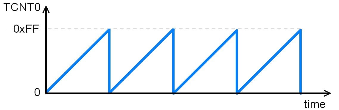
- TCNT0: Timer / Counter Register 0
It is an 8-bit register. It counts up with each pulse.
2. TCCR0: Timer / Counter Control register 0
This is an 8-bit register used for the operation mode and the clock source selection.

Bit 7- FOC0: Force compare match
Write only a bit, which can be used while generating a wave. Writing 1 to this bit causes the wave generator to act as if a compare match has occurred.
Bit 6, 3 - WGM00, WGM01: Waveform Generation Mode
| WGM00 | WGM01 | Timer0 mode selection bit |
|---|---|---|
| 0 | 0 | Normal |
| 0 | 1 | CTC (Clear timer on Compare Match) |
| 1 | 0 | PWM, Phase correct |
| 1 | 1 | Fast PWM |
Bit 5:4 - COM01:00: Compare Output Mode
These bits control the waveform generator. We will see this in the compare mode of the timer.
Bit 2:0 - CS02:CS00: Clock Source Select
These bits are used to select a clock source. When CS02: CS00 = 000, then timer is stopped. As it gets a value between 001 to 101, it gets a clock source and starts as the timer.
| CS02 | CS01 | CS00 | Description |
|---|---|---|---|
| 0 | 0 | 0 | No clock source (Timer / Counter stopped) |
| 0 | 0 | 1 | clk (no pre-scaling) |
| 0 | 1 | 0 | clk / 8 |
| 0 | 1 | 1 | clk / 64 |
| 1 | 0 | 0 | clk / 256 |
| 1 | 0 | 1 | clk / 1024 |
| 1 | 1 | 0 | External clock source on T0 pin. Clock on falling edge |
| 1 | 1 | 1 | External clock source on T0 pin. Clock on rising edge. |
3. TIFR: Timer Counter Interrupt Flag register

Bit 0 - TOV0: Timer0 Overflow flag
0 = Timer0 did not overflow
1 = Timer0 has overflown (going from 0xFF to 0x00)
Bit 1 - OCF0: Timer0 Output Compare flag
0 = Compare match did not occur
1 = Compare match occurred
Bit 2 - TOV1: Timer1 Overflow flag
Bit 3 - OCF1B: Timer1 Output Compare B match flag
Bit 4 - OCF1A: Timer1 Output Compare A match flag
Bit 5 - ICF1: Input Capture flag
Bit 6 - TOV2: Timer2 Overflow flag
Bit 7 - OCF2: Timer2 Output Compare match flag
Timer0 Overflow
Normal mode: When the counter overflows i.e. goes from 0xFF to 0x00, the TOV0 flag is set.
Creating Delay Using Timer0
Steps to Program Delay using Timer0
1. Load the TCNT0 register with the initial value (let’s take 0x25).
2. For normal mode and the pre-scaler option of the clock, set the value in the TCCR0 register. As soon as the clock Prescaler value gets selected, the timer/counter starts to count, and each clock tick causes the value of the timer/counter to increment by 1.
3.Timer keeps counting up, so keep monitoring for timer overflow i.e. TOV0 (Timer0 Overflow) flag to see if it is raised.
4. Stop the timer by putting 0 in the TCCR0 i.e. the clock source will get disconnected and the timer/counter will get stopped.
5. Clear the TOV0 flag. Note that we have to write 1 to the TOV0 bit to clear the flag.
6. Return to the main function.
Program for Timer Delay
/*
  Generating delay using ATmega16 Timer0
  http://www.electronicwings.com
*/


#include <avr/io.h>

void T0delay();

int main(void)
{
	DDRB = 0xFF;		/* PORTB as output*/

    	while(1)  		/* Repeat forever*/
    	{
		PORTB=0x55;
		T0delay();  	/* Give some delay */
		PORTB=0xAA;
		T0delay();
    	}
}

void T0delay()
{
	TCNT0 = 0x25;  		/* Load TCNT0*/
	TCCR0 = 0x01;  		/* Timer0, normal mode, no pre-scalar */

	while((TIFR&0x01)==0);  /* Wait for TOV0 to roll over */
	TCCR0 = 0;
	TIFR = 0x1;  		/* Clear TOV0 flag*/
}
The time delay generated by above code
As Fosc = 8 MHz
T = 1 / Fosc = 0.125 μs
Therefore, the count increments by every 0.125 μs.
In above code, the number of cycles required to roll over are:
0xFF - 0x25= 0xDA i.e. decimal 218
Add one more cycle as it takes to roll over and raise TOV0 flag: 219
Total Delay = 219 x 0.125 μs = 27.375 μs
Example
Let us generate a square waveform having 10 ms high and 10 ms low time:
First, we have to create a delay of 10 ms using timer0.
*Fosc = 8 MHz
Use the pre-scalar 1024, so the timer clock source frequency will be,
8 MHz / 1024 = 7812.5 Hz
Time of 1 cycle = 1 / 7812.5 = 128 μs
Therefore, for a delay of 10 ms, number of cycles required will be,
10 ms / 128 μs = 78 (approx)
We need 78 timer cycles to generate a delay of 10 ms. Put the value in TCNT0 accordingly.
Value to load in TCNT0 = 256 – 78 (78 clock ticks to overflow the timer)
= 178 i.e. 0xB2 in hex
Thus, if we load 0xB2 in the TCNT0 register, the timer will overflow after 78 cycles i.e. precisely after a delay of 10 ms.
*Note - All calculations are done by considering 8 MHz CPU frequency. If you are using another value of CPU frequency, modify the calculations accordingly; otherwise, the delay will mismatch.
Program for 10ms Delay Using Timer0
/*
  Generating a delay of 10 ms using ATmega16 Timer0
  www.electronicwings.com
 */


#include <avr/io.h>

void T0delay();

int main(void)
{
	DDRB = 0xFF;		/* PORTB as output */
	PORTB=0;
    	while(1)  		/* Repeat forever */
    	{
		PORTB= ~ PORTB;
		T0delay();
    	}
}

void T0delay()
{
	TCCR0 = (1<<CS02) | (1<<CS00); /* Timer0, normal mode, /1024 prescalar */
	TCNT0 = 0xB2;  		/* Load TCNT0, count for 10ms */
	while((TIFR&0x01)==0);  /* Wait for TOV0 to roll over */
	TCCR0 = 0;
	TIFR = 0x1;  		/* Clear TOV0 flag */
}
Timer Interrupt
TIMSK: Timer / Counter Interrupt Mask Register

We have to set the TOIE0 (Timer0 Overflow Interrupt Enable) bit in the TIMSK register to set the timer0 interrupt so that as soon as the Timer0 overflows, the controller jumps to the Timer0 interrupt routine.
Timer0 Interrupt Program
/*
  	Generating 10 ms delay pulse on PORTB using ATmega16 Timer interrupt
  	www.electronicwings.com
 */


#include <avr/io.h>
#include <avr/interrupt.h>

/* timer0 overflow interrupt */
ISR(TIMER0_OVF_vect)
{
	PORTB=~PORTB;		/* Toggle PORTB */
	TCNT0 = 0xB2;
}


int main( void )
{
	DDRB=0xFF;  		/* Make port B as output */

	sei();
	TIMSK=(1<<TOIE0);  	/* Enable Timer0 overflow interrupts */

	TCNT0 = 0xB2;  		/* Load TCNT0, count for 10ms*/
	TCCR0 = (1<<CS02) | (1<<CS00); /* Start timer0 with /1024 prescaler*/
	while(1);
}
Video
Components Used |
||
|---|---|---|
| ATmega 16 ATmega 16 |
X 1 | |
| Atmega32 Atmega32 |
X 1 | |