Introduction
 LCD 16x2
LCDs (Liquid Crystal Displays) are used for displaying status or parameters in embedded systems.
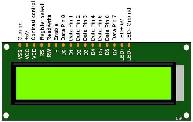
LCD 16x2 is 16 pin device which has 8 data pins (D0-D7) and 3 control pins (RS, RW, EN). The remaining 5 pins are for supply and backlight for the LCD.
The control pins help us configure the LCD in command mode or data mode. They also help configure read mode or write mode and also when to read or write.
LCD 16x2 can be used in 4-bit mode or 8-bit mode depending on the requirement of the application. In order to use it we need to send certain commands to the LCD in command mode and once the LCD is configured according to our need, we can send the required data in data mode.
For more information about LCD 16x2 and how to use it, refer the topic LCD 16x2 display module in the sensors and modules section.
Interfacing Diagram
 Interfacing 16x2 LCD With LPC2148
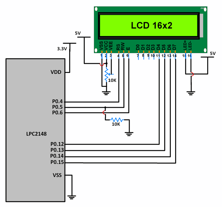
Since we are using LCD in 4-bit mode, we require only 4 Data pins.
LCD Data pins D4-D7 are connected to pins P0.12-P0.15 of Port 0.
LCD control pins RS, RW and EN are connected to P0.4, P0.5 P0.6 respectively.
LCD programming
1. Initializing the LCD
void LCD_INIT(void)
{
	IO0DIR = 0x0000FFF0; /* P0.12 to P0.15 LCD Data. P0.4,5,6 as RS RW and EN */
	delay_ms(20);
	LCD_CMD(0x02);  /* Initialize lcd in 4-bit mode */
	LCD_CMD(0x28);  /* 2 lines */
	LCD_CMD(0x0C);   /* Display on cursor off */
	LCD_CMD(0x06);  /* Auto increment cursor */
	LCD_CMD(0x01);   /* Display clear */
	LCD_CMD(0x80);  /* First line first position */
}
2. Command Write Function
- For command mode, RS = 0.
- RW = 0 for write.
- High to low EN pulse of minimum 450ns high pulse width.
void LCD_CMD(char command)
{
	IO0PIN = ( (IO0PIN & 0xFFFF00FF) | ((command & 0xF0)<<8) ); /* Upper nibble of command */
	IO0SET = 0x00000040; /* EN = 1 */
	IO0CLR = 0x00000030; /* RS = 0, RW = 0 */
	delay_ms(5);
	IO0CLR = 0x00000040; /* EN = 0, RS and RW unchanged(i.e. RS = RW = 0)	 */
	delay_ms(5);
	IO0PIN = ( (IO0PIN & 0xFFFF00FF) | ((command & 0x0F)<<12) ); /* Lower nibble of command */
	IO0SET = 0x00000040; /* EN = 1 */
	IO0CLR = 0x00000030; /* RS = 0, RW = 0 */
	delay_ms(5);
	IO0CLR = 0x00000040; /* EN = 0, RS and RW unchanged(i.e. RS = RW = 0)	 */
	delay_ms(5);
}
3. Data Write Function (Single Character)
- For data mode, RS = 1.
- RW = 0 for write.
- High to low EN pulse of minimum 450ns high pulse width.
void LCD_CHAR (char msg)
{
		IO0PIN = ( (IO0PIN & 0xFFFF00FF) | ((msg& 0xF0)<<8) );
		IO0SET = 0x00000050; /* RS = 1, EN = 1 */
		IO0CLR = 0x00000020; /* RW = 0 */
		delay_ms(2);
		IO0CLR = 0x00000040; /* EN = 0, RS and RW unchanged(i.e. RS = 1, RW = 0) */
		delay_ms(5);
		IO0PIN = ( (IO0PIN & 0xFFFF00FF) | ((msg& 0x0F)<<12) );
		IO0SET = 0x00000050; /* RS = 1, EN = 1 */
		IO0CLR = 0x00000020; /* RW = 0 */
		delay_ms(2);
		IO0CLR = 0x00000040; /* EN = 0, RS and RW unchanged(i.e. RS = 1, RW = 0) */
		delay_ms(5);
}
4. Data Write Function(String)
- For data mode, RS = 1.
- RW = 0 for write.
- High to low EN pulse of minimum 450ns high pulse width.
void LCD_STRING (char* msg)
{
	uint8_t i=0;
	while(msg[i]!=0)
	{
		IO0PIN = ( (IO0PIN & 0xFFFF00FF) | ((msg[i] & 0xF0)<<8) );
		IO0SET = 0x00000050; /* RS = 1, EN = 1 */
		IO0CLR = 0x00000020; /* RW = 0 */
		delay_ms(2);
		IO0CLR = 0x00000040; /* EN = 0, RS and RW unchanged(i.e. RS = 1, RW = 0) */
		delay_ms(5);
		IO0PIN = ( (IO0PIN & 0xFFFF00FF) | ((msg[i] & 0x0F)<<12) );
		IO0SET = 0x00000050; /* RS = 1, EN = 1 */
		IO0CLR = 0x00000020; /* RW = 0 */
		delay_ms(2);
		IO0CLR = 0x00000040; /* EN = 0, RS and RW unchanged(i.e. RS = 1, RW = 0) */
		delay_ms(5);
		i++;
	}
}
OR
void LCD_STRING (char* msg)
{
	uint8_t i=0;
	while(msg[i]!=0)
	{
		LCD_CHAR(msg[i]);
		i++;
	}
}
Example
A program for displaying a string on LCD 16x2 using 4-bit mode.
Program
/*
  16x2 LCD (4-bit mode) interfacing with LPC2148(ARM7)
  http://www.electronicwings.com/arm7/lcd-16x2-interfacing-with-lpc2148-4-bit-mode
*/

#include <lpc214x.h>
#include <stdint.h>
#include <stdlib.h>
#include <stdio.h>

void delay_ms(uint16_t j) /* Function for delay in milliseconds */
{
    uint16_t x,i;
	for(i=0;i<j;i++)
	{
    for(x=0; x<6000; x++);    /* loop to generate 1 millisecond delay with Cclk = 60MHz */
	}
}

void LCD_CMD(char command)
{
	IO0PIN = ( (IO0PIN & 0xFFFF00FF) | ((command & 0xF0)<<8) ); /* Upper nibble of command */
	IO0SET = 0x00000040; /* EN = 1 */
	IO0CLR = 0x00000030; /* RS = 0, RW = 0 */
	delay_ms(5);
	IO0CLR = 0x00000040; /* EN = 0, RS and RW unchanged(i.e. RS = RW = 0)	 */
	delay_ms(5);
	IO0PIN = ( (IO0PIN & 0xFFFF00FF) | ((command & 0x0F)<<12) ); /* Lower nibble of command */
	IO0SET = 0x00000040; /* EN = 1 */
	IO0CLR = 0x00000030; /* RS = 0, RW = 0 */
	delay_ms(5);
	IO0CLR = 0x00000040; /* EN = 0, RS and RW unchanged(i.e. RS = RW = 0)	 */
	delay_ms(5);

}

void LCD_INIT(void)
{
	IO0DIR = 0x0000FFF0; /* P0.12 to P0.15 LCD Data. P0.4,5,6 as RS RW and EN */
	delay_ms(20);
	LCD_CMD(0x02);  /* Initialize lcd in 4-bit mode */
	LCD_CMD(0x28);  /* 2 lines */
	LCD_CMD(0x0C);   /* Display on cursor off */
	LCD_CMD(0x06);  /* Auto increment cursor */
	LCD_CMD(0x01);   /* Display clear */
	LCD_CMD(0x80);  /* First line first position */
}

void LCD_STRING (char* msg)
{
	uint8_t i=0;
	while(msg[i]!=0)
	{
		IO0PIN = ( (IO0PIN & 0xFFFF00FF) | ((msg[i] & 0xF0)<<8) );
		IO0SET = 0x00000050; /* RS = 1, EN = 1 */
		IO0CLR = 0x00000020; /* RW = 0 */
		delay_ms(2);
		IO0CLR = 0x00000040; /* EN = 0, RS and RW unchanged(i.e. RS = 1, RW = 0) */
		delay_ms(5);
		IO0PIN = ( (IO0PIN & 0xFFFF00FF) | ((msg[i] & 0x0F)<<12) );
		IO0SET = 0x00000050; /* RS = 1, EN = 1 */
		IO0CLR = 0x00000020; /* RW = 0 */
		delay_ms(2);
		IO0CLR = 0x00000040; /* EN = 0, RS and RW unchanged(i.e. RS = 1, RW = 0) */
		delay_ms(5);
		i++;
	}
}

void LCD_CHAR (char msg)
{
		IO0PIN = ( (IO0PIN & 0xFFFF00FF) | ((msg & 0xF0)<<8) );
		IO0SET = 0x00000050; /* RS = 1, EN = 1 */
		IO0CLR = 0x00000020; /* RW = 0 */
		delay_ms(2);
		IO0CLR = 0x00000040; /* EN = 0, RS and RW unchanged(i.e. RS = 1, RW = 0) */
		delay_ms(5);
		IO0PIN = ( (IO0PIN & 0xFFFF00FF) | ((msg & 0x0F)<<12) );
		IO0SET = 0x00000050; /* RS = 1, EN = 1 */
		IO0CLR = 0x00000020; /* RW = 0 */
		delay_ms(2);
		IO0CLR = 0x00000040; /* EN = 0, RS and RW unchanged(i.e. RS = 1, RW = 0) */
		delay_ms(5);
}

int main(void)
{
	uint8_t j;
	j = 0;
	char val_j[3];
	LCD_INIT();
	LCD_STRING("Good Day!");
	LCD_CMD(0xC0);
	LCD_STRING("Val of j is:");
	for(j=0;j<10;j++)
	{
		sprintf(val_j,"%d ",j);
		LCD_STRING(val_j);
		delay_ms(100);
		LCD_CMD(0xCC);
	}
	return 0;
}
Output
Components Used |
||
|---|---|---|
| ARM7 LPC2148 ARM7 LPC2148 |
X 1 | |
| LCD16x2 Display LCD16x2 Display |
X 1 | |
| Breadboard Breadboard |
X 1 | |
Downloads |
||
|---|---|---|
|
|
LCD16x2_4bit_uVision_Project | Download |