Introduction
LPC2148 Timer includes input capture feature, using which we can capture/trap the timer counter value on events like rising edge (positive going) and falling edge (negative going). With this function, we can measure frequency, pulse width, duty cycle of the input signal.
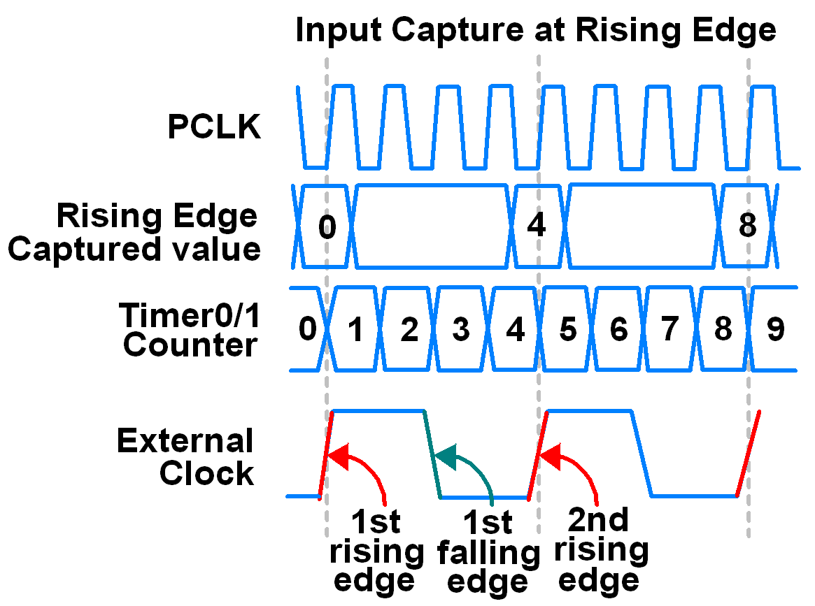
For example, suppose we set input capture mode at every rising edge as shown in above figure. Then, timer counter value gets copied to capture register every time external clock rising edge occurs on capture pin.
Now, we get time period as,
Time period = 2nd rising edge – 1st rising edge
From above figure,
Time period = 4 – 0 = 4 PCLK clocks
Now we can calculate frequency, duty cycle of the external clock if we know the frequency of the peripheral clock (PCLK) that is counted by timer counter.
i.e. Frequency = 1 / Time period
Duty cycle = (1st falling edge – 1st rising edge) / Time period
The Capture Control Register decides which event is to be recorded (e.g. rising/falling edge or both) and whether an interrupt is to be generated.
On each capture event on a capture pin, corresponding capture register gets copied with the TC (Timer Counter) value.
ARM LPC2148 Capture pins
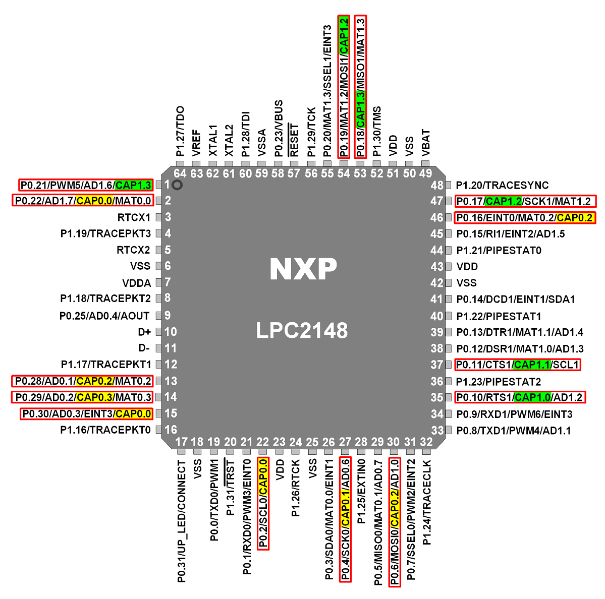
- CAP0.0 (3 pins): P0.2, P0.22 and P0.30
- CAP0.1 (1 pin): P0.4
- CAP0.2 (3 pin): P0.6, P0.16 and P0.28
- CAP0.3 (1 pin): P0.29
- CAP1.0 (1 pin): P0.10
- CAP1.1 (1 pin): P0.11
- CAP1.2 (2 pins): P0.17 and P0.19
- CAP1.3 (2 pins): P0.18 and P0.21
Let’s take a quick look at the LPC2148 timer0 registers that are needed for capture operation. Timer0 and timer1 registers are similar in their operation and have similar structures, but differ in names.
Timer0 Registers
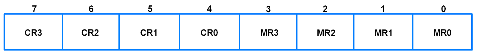
1. T0IR (Timer0 Interrupt Register)
- It is an 8-bit read-write register.
- Consists of 4 bits for match register interrupts and 4 bits for compare register interrupts.
- If interrupt is generated, then the corresponding bit in this register will be high, otherwise, it will be low.
- Writing a 1 to any bit of this register will reset that interrupt. Writing a 0 has no effect.
2. T0TCR (Timer0 Timer Control Register)
- It is an 8-bit read-write register.
- It is used to control the operation of the timer counter.
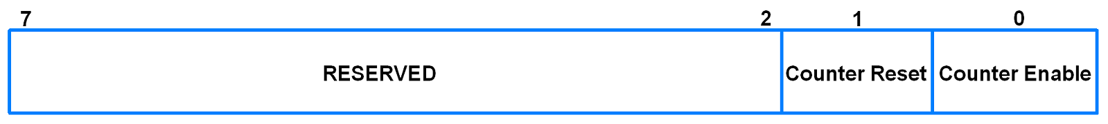
- Bit 0 – Counter Enable
0 = Counters are disabled
1 = Timer counter and Prescale counter are enabled for counting - Bit 1 – Counter Reset
0 = Counter not reset
1 = Timer counter and Prescale counter are synchronously reset on next positive edge of PCLK
3. T0CR0-T0CR3 (Timer0 Capture Registers)
- These are 32-bit read only registers.
- Each capture register is associated with a capture pin and it may be loaded with the TC value when a specific event occurs on the capture pin.
- The Capture Control Register decides whether capture function is enabled and on which event (rising edge or falling edge or both) it happens.
4. T0TC (Timer0 Timer Counter)
- It is a 32-bit timer counter.
- It is incremented when the Prescale Counter (PC) reaches its maximum value held by Prescaler Register (PR).
- Note: When TC overflow occurs, it does not generate any overflow interrupt. Alternatively, we can use match register to detect overflow event if needed.
5. T0CCR (Timer0 Capture Control Register)
- It is a 16-bit register.
- It is used to decide whether one of the capture registers is to be loaded with the value in TC when capture event occurs and whether an interrupt is generated when the event occurs.
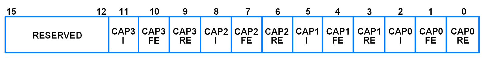
- Setting both the rising bit and falling bit at the same time is a valid configuration.
- Bit 0 – CAP0RE (Capture on Rising Edge)
0 = This feature is disabled
1 = Rising Edge i.e. positive going (sequence of 0 followed by 1) on the CAP0.0 will cause CR0 to be loaded with contents of TC - Bit 1 – CAP0FE (Capture on Falling Edge)
0 = This feature is disabled
1 = Falling Edge i.e. negative going (sequence of 1 followed by 0) on the CAP0.0 will cause CR0 to be loaded with contents of TC - Bit 2 – CAP0I (Interrupt on Capture)
0 = This feature is disabled
1 = An interrupt will be generated when CR0 is loaded with the TC value
CAP1, CAP2 and CAP3 bits function in the same manner as CAP0 bits.
Example
Let’s write a code to capture the signal present on capture pin CAP0.0 (P0.2) and find out its frequency and period and display it on PC terminal using UART0.
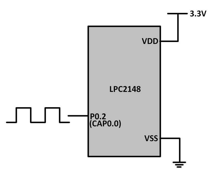
Signal to be captured is applied to P0.2.
To find out the period of the input signal, we need to capture 2 consecutive rising or falling edges of the signal. The difference in time between these two events will be the number of PCLK pulses between the two events.
Hence, the period will be number of pulses * width of each pulse.
Frequency is (1/period).
Program for Input capture mode using LPC2148
/*
  Input capture mode for timer in LPC2148(ARM7)
  http://www.electronicwings.com/arm7/lpc2148-timer-input-capture-mode
*/

#include <lpc214x.h>
#include <stdint.h>
#include <stdio.h>

uint8_t count;
uint32_t rising_edge1, falling_edge, rising_edge2;

void delay_ms(uint16_t j)
{
    uint16_t x,i;
	for(i=0;i<j;i++)
	{
    for(x=0; x<6000; x++);    /* loop to generate 1 milisecond delay with Pclk=15MHz */
	}
}

__irq void T0_ISR (void)
{
	if(count == 0)
	{
		rising_edge1 = T0CR0;
		T0CCR = 0x0006; /* Capture mode Cap0.0, capture on falling edge with interrupt */
	}
	else if(count == 1)
	{
		falling_edge = T0CR0;
		T0CCR = 0x0005; /* Capture mode Cap0.0, capture on rising edge with interrupt */
	}
	else if(count == 2)
	{
		rising_edge2 = T0CR0;
	}
	count++;
	T0IR = ( T0IR | 0x10 );
	VICVectAddr = 0x00;
}

void UART0_init(void)
{
	PINSEL0 = PINSEL0 | 0x00000005;	/* Enable UART0 Rx0 and Tx0 pins of UART0 */
	U0LCR = 0x83;	/* DLAB = 1, 1 stop bit, 8-bit character length*/
	U0DLM = 0x00;	/* For baud rate of 9600 with Pclk = 30MHz */
	U0DLL = 0xC3;	/* We get these values of U0DLL and U0DLM from formula */
	U0LCR = 0x03; /* DLAB = 0 */
}

void UART0_TxChar(char ch) //A function to send a byte on UART0
{
	U0THR = ch;
	while( (U0LSR & 0x40) == 0 );	/* Wait till THRE bit becomes 1 which tells that transmission is completed */
}

void UART0_SendString(char* str) /* A function to send string on UART0 */
{
	uint8_t i = 0;
	while( str[i] != '\0' )
	{
		UART0_TxChar(str[i]);
		i++;
	}
}

int main (void)
{
	//uint32_t period;
	float period;
	float frequency;
	char string1[20];
	char string2[20];
	UART0_init();
	VPBDIV	= 0x00000002; /* For Pclk = 30MHz */
	/* We have configured Cclk=60MHz. Above instruction makes Pclk = Cclk/2 = 30MHz */
	PINSEL0 = PINSEL0 | 0x00000020; /* Configure P0.2 as Capture 0.0 */
	VICVectAddr0 = (unsigned) T0_ISR; /* T0 ISR Address */
	VICVectCntl0 = 0x00000024; /* Enable T0 IRQ slot */
	VICIntEnable = 0x00000010; /* Enable T0 interrupt */
	VICIntSelect = 0x00000000; /* T0 configured as IRQ */
	T0TCR = 0x02; /* Reset TC and PR */
	T0CCR = 0x0005; /* Capture mode Cap0.0, capture on rising edge with interrupt */
	T0PR = 0x00; /* No pre-scalar */
	T0TCR = 0x01; /* Enable timer */
	count = 0;
	while (1)
	{
		if(count>2)
		{
			VICIntEnable = 0x00000000; /* Disable all interrupts */
			T0CCR = 0x00000000;
			if(rising_edge1<falling_edge<rising_edge2)
			{
				period = ((rising_edge2 - rising_edge1)/1.0);
				frequency = (30000000/period);
				sprintf(string1,"Period = %f \r\n",period);
				UART0_SendString(string1);
				sprintf(string2,"Frequency = %f \r\n",frequency);
				UART0_SendString(string2);
			}
			count = 0;
			VICIntEnable = 0x00000010;
			T0CCR 		= 0x00000005;
			delay_ms(1000);
		}
	}
}
Video
Components Used |
||
|---|---|---|
| ARM7 LPC2148 ARM7 LPC2148 |
X 1 | |
| CP2103 USB TO UART BRIDGE CP2103 is single chip USB to UART Bridge. It supports USB 2.0 protocol. |
X 1 | |