Introduction
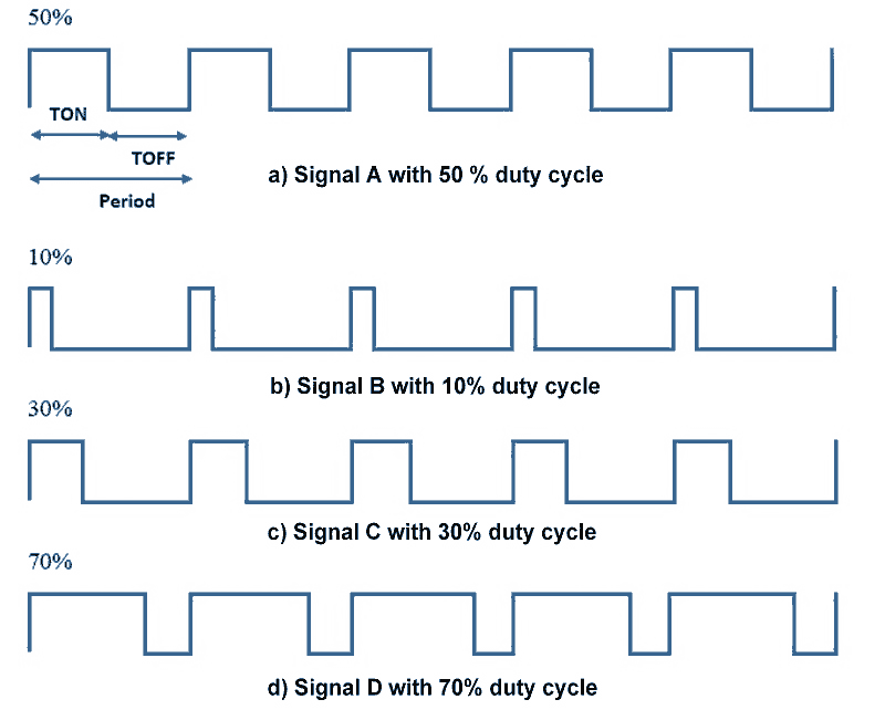
Pulse Width Modulation (PWM) is a technique by which width of a pulse is varied while keeping the frequency constant.
A period of a pulse consists of an ON cycle (HIGH) and an OFF cycle (LOW). The fraction for which the signal is ON over a period is known as duty cycle.
Duty Cycle (In %) = x 100
E.g. Consider a pulse with a period of 10ms which remains ON (high) for 2ms.The duty cycle of this pulse will be
D = (2ms / 10ms) x 100 = 20%
Through PWM technique, we can control the power delivered to the load by using ON-OFF signal.
Duty cycle in pwm are shown below.
LPC2148 has PWM peripheral through which we can generate multiple PWM signals on PWM pins. Also, LPC2148 supports two types of controlled PWM outputs as,
- Single Edge Controlled PWM Output
Only falling edge position can be controlled. - Double Edge Controlled PWM Output
Both Rising and Falling edge positions can be controlled.
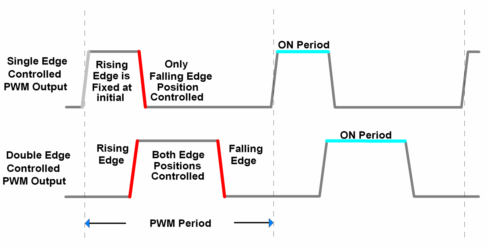
Single Edge Controlled PWM : All the rising (positive going) edges of the output waveform are positioned/fixed at the beginning of the PWM period. Only falling (negative going) edge position can be controlled to vary the pulse width of PWM.
Double Edge Controlled PWM : All the rising (positive going) and falling (negative going) edge positions can be controlled to vary the pulse width of PWM. Both the rising as well as the falling edges can be positioned anywhere in the PWM period.
LPC2148 PWM
- The PWM in LPC2148 is based on standard 32-bit Timer Counter, i.e. PWMTC (PWM Timer Counter). This Timer Counter counts the cycles of peripheral clock (PCLK).
- Also, we can scale this timer clock counts using 32-bit PWM Prescale Register (PWMPR).
- LPC2148 has 7 PWM match registers (PWMMR0 – PWMMR06).
- One match register (PWMMR0) is used to set PWM frequency.
- Remaining 6 match registers are used to set PWM width for 6 different PWM signals in Single Edge Controlled PWM or 3 different PWM signals in Double Edge Controlled PWM.
- Whenever PWM Timer Counter (PWMTC) matches with these Match Registers then, PWM Timer Counter resets, or stops, or generates match interrupt, depending upon settings in PWM Match Control Register(PWMMCR).
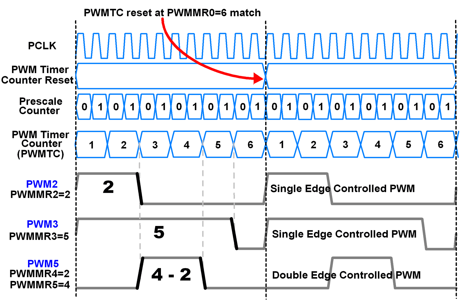
As shown in above figure, PWMMR0 = 6 i.e. PWM period is 6 counts, after which PWM Timer Counter resets.
PWM2 & PWM3 are configured as Single Edge Controlled PWM and PWM5 is configured as Double Edge Controlled PWM.
Prescaler is set to increment PWM Timer Counter after every two Peripheral clocks (PCLK).
Match registers (PWMMR2 & PWMMR3) are used to set falling edge position for PWM2 & PWM3.
PWMMR4 & PWMMR5 are used to set rising & falling edge positions respectively for PWM5.
Let’s see the different PWM that can be generated using LPC2148
The table given below shows when the PWM is Set (Rising Edge) and Reset (Falling Edge) for different PWM channels using 7 Match Register.
| PWM Channel | Single Edge Controlled | Double Edge Controlled | ||
| Set by | Reset by | Set by | Reset by | |
| 1 | Match 0 | Match 1 | Match 0 | Match 1 |
| 2 | Match 0 | Match 2 | Match 1 | Match 2 |
| 3 | Match 0 | Match 3 | Match 2 | Match 3 |
| 4 | Match 0 | Match 4 | Match 3 | Match 4 |
| 5 | Match 0 | Match 5 | Match 4 | Match 5 |
| 6 | Match 0 | Match 6 | Match 5 | Match 6 |
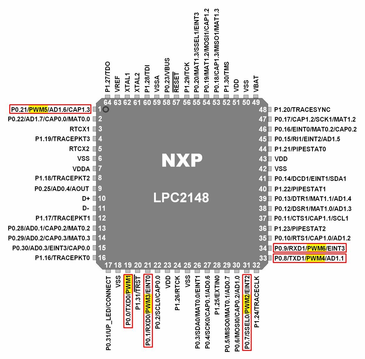
ARM LPC2148 PWM Pin Diagram
Let’s see the various PWM registers that are useful in controlling and generating PWM.
PWM Registers configuration for LPC2148
1. PWMIR (PWM Interrupt Register)
- It is a 16-bit register.
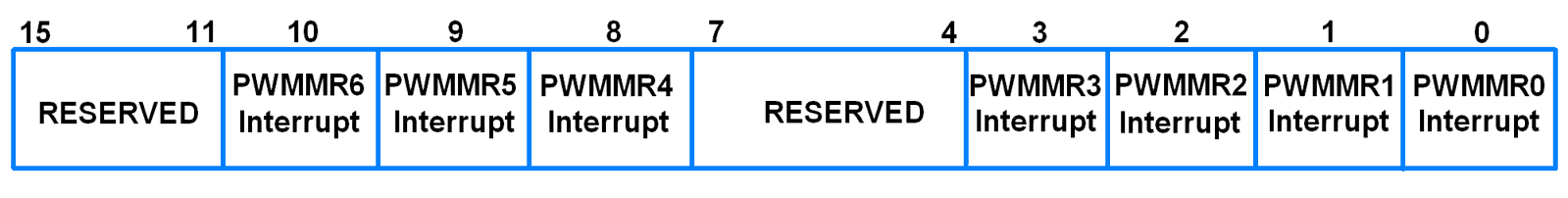
- It has 7 interrupt bits corresponding to the 7 PWM match registers.
- If an interrupt is generated, then the corresponding bit in this register becomes HIGH.
- Otherwise the bit will be LOW.
- Writing a 1 to a bit in this register clears that interrupt.
- Writing a 0 has no effect.
2. PWMTCR (PWM Timer Control Register)
- It is an 8-bit register.
- It is used to control the operation of the PWM Timer Counter.

Bit 0 – Counter Enable
When 1, PWM Timer Counter and Prescale Counter are enabled.
When 0, the counters are disabled.
Bit 1 – Counter Reset
When 1, the PWM Timer Counter and PWM Prescale Counter are synchronously reset on next positive edge of PCLK.
Counter remains reset until this bit is returned to 0.
Bit 3 – PWM Enable
This bit always needs to be 1 for PWM operation. Otherwise PWM will operate as a normal timer.
When 1, PWM mode is enabled and the shadow registers operate along with match registers.
A write to a match register will have no effect as long as corresponding bit in PWMLER is not set.
Note : PWMMR0 must always be set before PWM is enabled, otherwise match event will not occur to cause shadow register contents to become effective.
3. PWMTC (PWM Timer Counter)
- It is a 32-bit register.
- It is incremented when the PWM Prescale Counter (PWMPC) reaches its terminal count.
4. PWMPR (PWM Prescale Register)
- It is a 32-bit register.
- It holds the maximum value of the Prescale Counter.
5. PWMPC (PWM Prescale Counter)
- It is a 32-bit register.
- It controls the division of PCLK by some constant value before it is applied to the PWM Timer Counter.
- It is incremented on every PCLK.
- When it reaches the value in PWM Prescale Register, the PWM Timer Counter is incremented and PWM Prescale Counter is reset on next PCLK.
6. PWMMR0-PWMMR6 (PWM Match Registers)
- These are 32-bit registers.
- The values stored in these registers are continuously compared with the PWM Timer Counter value.
- When the two values are equal, the timer can be reset or stop or an interrupt may be generated.
- The PWMMCR controls what action should be taken on a match.
7. PWMMCR (PWM Match Control Register)
- It is a 32-bit register.
- It controls what action is to be taken on a match between the PWM Match Registers and PWM Timer Counter.
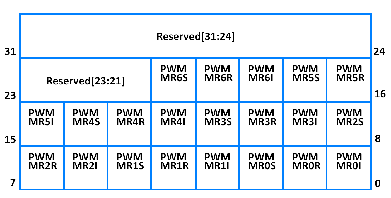
- Bit 0 – PWMMR0I (PWM Match register 0 interrupt)
0 = This interrupt is disabled
1 = Interrupt on PWMMR0. An interrupt is generated when PWMMR0 matches the value in PWMTC - Bit 1 – PWMMR0R (PWM Match register 0 reset)
0 = This feature is disabled
1 = Reset on PWMMR0. The PWMTC will be reset if PWMMR0 matches it - Bit 2 – PWMMR0S (PWM Match register 0 stop)
0 = This feature is disabled
1 = Stop on PWMMR0. The PWMTC and PWMPC is stopped and Counter Enable bit in PWMTCR is set to 0 if PWMMR0 matches PWMTC - PWMMR1, PWMMR2, PWMMR3, PWMMR4, PWMMR5 and PWMMR6 has same function bits (stop, reset, interrupt) as in PWMMR0.
8. PWMPCR (PWM Control Register)
- It is a 16-bit register.
- It is used to enable and select each type of PWM.

- Bit 2 – PWMSEL2
0 = Single edge controlled mode for PWM2
1 = Double edge controlled mode for PWM2 - All other PWMSEL bits have similar operation as PWMSEL2 above.
- Bit 10 – PWMENA2
0 = PWM2 output disabled
1 = PWM2 output enabled - All other PWMENA bits have similar operation as PWMENA2 above.
9. PWMLER (PWM Latch Enable Register)
- It is an 8-bit register.
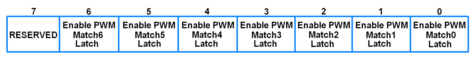
- It is used to control the update of the PWM Match Registers when they are used for PWM generation.
- When a value is written to a PWM Match Register while the timer is in PWM mode, the value is held in the shadow register. The contents of the shadow register are transferred to the PWM Match Register when the timer resets (PWM Match 0 event occurs) and if the corresponding bit in PWMLER is set.
- Bit 6 – Enable PWM Match 6 Latch
Writing a 1 to this bit allows the last written value to PWMMR6 to become effective when timer next is reset by the PWM match event. - Similar description as that of Bit 6 for the remaining bits.
Steps for PWM generation
- Reset and disable PWM counter using PWMTCR
- Load prescale value according to need of application in the PWMPR
- Load PWMMR0 with a value corresponding to the time period of your PWM wave
- Load any one of the remaining six match registers (two of the remaining six match registers for double edge controlled PWM) with the ON duration of the PWM cycle. (PWM will be generated on PWM pin corresponding to the match register you load the value with).
- Load PWMMCR with a value based on the action to be taken in the event of a match between match register and PWM timer counter.
- Enable PWM match latch for the match registers used with the help of PWMLER
- Select the type of PWM wave (single edge or double edge controlled) and which PWMs to be enabled using PWMPCR
- Enable PWM and PWM counter using PWMTCR
Example 1
Let’s write a Program to generate a double edge controlled PWM on PWM3 (P0.1).
.png)
Program for double edge controlled PWM generation for LPC2148
/*
  double edge controlled PWM generation in LPC2148(ARM7)
  http://www.electronicwings.com/arm7/lpc2148-pwm
*/

#include <lpc214x.h>

__irq void PWM_ISR (void)
{
	if ( PWMIR & 0x0001 )	/* If interrupt due to PWM0 */
	{
		PWMIR = 0x0001;	/* Clear PWM0 interrupt */
	}

	if ( PWMIR & 0x0002 )	/* If interrupt due to PWM1 */
	{
		PWMIR = 0x0002;	/* Clear PWM1 interrupt */
	}

	if ( PWMIR & 0x0004 )	/* If interrupt due to PWM2 */
	{
		PWMIR = 0x0004;	/* Clear PWM2 interrupt */
	}

	if ( PWMIR & 0x0008 )	/* If interrupt due to PWM3 */
	{
		PWMIR = 0x0008;	/* Clear PWM3 interrupt */
	}
	VICVectAddr = 0x00000000;
}


int main (void)
{
	VPBDIV		= 0x00000002;
	PINSEL0 = PINSEL0 | 0x00008008; /* Configure P0.1 and P0.7 as PWM3 and PWM2 respectively */
	VICVectAddr0 = (unsigned) PWM_ISR; /* PWM ISR Address */
	VICVectCntl0 = (0x00000020 | 8); /* Enable PWM IRQ slot */
	VICIntEnable = VICIntEnable | 0x00000100; /* Enable PWM interrupt */
	VICIntSelect = VICIntSelect | 0x00000000; /* PWM configured as IRQ */


// For PWM3 double edge
	PWMTCR = 0x02;	/* Reset and disable counter for PWM */
	PWMPR = 0x1D;	/* Prescale value for 1usec, Pclk=30MHz*/
	PWMMR0 = 100000;	/* Time period of PWM wave, 100msec */
	PWMMR2 = 40000;	/* Rising edge of double edge controlled PWM */
	PWMMR3 = 80000;	/* Falling edge of double edge controlled PWM */
	PWMMCR = 0x00000243;	/* Reset and interrupt on MR0 match, interrupt on MR2 and MR3 match */
	PWMLER = 0x0D;	/* Latch enable for PWM3, PWM2 and PWM0 */
	PWMPCR = 0x0C08;	/* Enable PWM3, PWM2 and PWM0, double edge controlled PWM on PWM3 */
	PWMTCR = 0x09;	/* Enable PWM and counter */

	while (1);
}
Example 2
Let’s write a Program to generate a single edge controlled PWM with varying duty cycle on PWM3 (P0.1). We can see the effect of the varying duty cycle by connecting an LED to the pin P0.1. The intensity of the LED varies with the duty cycle of PWM.
.png)
Program for single edge controlled PWM generation for LPC2148
/*
  single edge controlled PWM generation in LPC2148(ARM7)
  http://www.electronicwings.com/arm7/lpc2148-pwm
*/

#include <lpc214x.h>
#include <stdint.h>

void delay_ms(uint16_t j)
{
    uint16_t x,i;
	for(i=0;i<j;i++)
	{
    for(x=0; x<6000; x++);    /* loop to generate 1 milisecond delay with Cclk = 60MHz */
	}
}

__irq void PWM_ISR (void)
{
	if ( PWMIR & 0x0001 )	/* If interrupt due to PWM0 */
	{
		PWMIR = 0x0001;	/* Clear PWM0 interrupt */
	}

	if ( PWMIR & 0x0002 )	/* If interrupt due to PWM1 */
	{
		PWMIR = 0x0002;	/* Clear PWM1 interrupt */
	}

	if ( PWMIR & 0x0004 )	/* If interrupt due to PWM2 */
	{
		PWMIR = 0x0004;	/* Clear PWM2 interrupt */
	}

	if ( PWMIR & 0x0008 )	/* If interrupt due to PWM3 */
	{
		PWMIR = 0x0008;	/* Clear PWM3 interrupt */
	}
	VICVectAddr = 0x00000000;
}


int main (void)
{
	uint32_t value;
	value = 1;
	VPBDIV		= 0x00000002;
	PINSEL0 = PINSEL0 | 0x00000008; /* Configure P0.1 as PWM3 */
	VICVectAddr0 = (unsigned) PWM_ISR; /* PWM ISR Address */
	VICVectCntl0 = (0x00000020 | 8); /* Enable PWM IRQ slot */
	VICIntEnable = VICIntEnable | 0x00000100; /* Enable PWM interrupt */
	VICIntSelect = VICIntSelect | 0x00000000; /* PWM configured as IRQ */

// For single edge controlled PWM3
	PWMTCR = 0x02; 	/* Reset and disable counter for PWM */
	PWMPR = 0x1D;	/* Prescale value for 1usec, Pclk=30MHz*/
	PWMMR0 = 1000;	/* Time period of PWM wave, 1msec */
	PWMMR3 = value;	/* Ton of PWM wave */
	PWMMCR = 0x00000203;	/* Reset and interrupt on MR0 match, interrupt on MR3 match */
	PWMLER = 0x09;	/* Latch enable for PWM3 and PWM0 */
	PWMPCR = 0x0800;	/* Enable PWM3 and PWM0, single edge controlled PWM on PWM3 */
	PWMTCR = 0x09;	/* Enable PWM and counter */

	while (1)
	{
		while (value != 999)
		{
			PWMMR3 = value;
			PWMLER = 0x08;
			delay_ms(5);
			value++;
		}
		while (value != 1)
		{
			PWMMR3 = value;
			PWMLER = 0x08;
			delay_ms(5);
			value--;
		}
	}
}
Video
Components Used |
||
|---|---|---|
| ARM7 LPC2148 ARM7 LPC2148 |
X 1 | |
| Breadboard Breadboard |
X 1 | |
| LED 5mm LED 5mm |
X 1 | |