Introduction to RTC
Real Time Clock (RTC) is a time counter that counts real time continuously.
- We can get present time details using RTC. It gives us time as well as date information.
- RTC is clocked by separate 32.768KHz oscillator to continuously keep track of current time.
- RTC is powered either by main system power or separately by battery backup in absence of main system power.
- Since RTC needs to be running continuously, it should be provided with battery backup in case of main system power failure. Otherwise, it can lose present time information.
- We can easily program the RTC with the current date and time information in the case of loss time and date information due to power failure.
- But this is not a feasible solution in real time systems once they are deployed into the market, where there are many time constraints on the tasks and timely decision making is important. In such cases, the RTC must not fail. This makes battery backup of utmost importance.
LPC2148 has an inbuilt RTC. LPC2148RTC can be clocked by a separate 32.768 KHz oscillator or by a programmable prescale divider based on the APB clock.
- It maintains a calendar and clock and provides seconds, minutes, hours, month, year, day of week, day of month and day of year.
- It has power supply pin that can be connected to a battery or to the main 3.3V.
- It uses little power in power down mode.
- And most important, it has Alarm functionality.
ARM LPC2148 RTC Pins
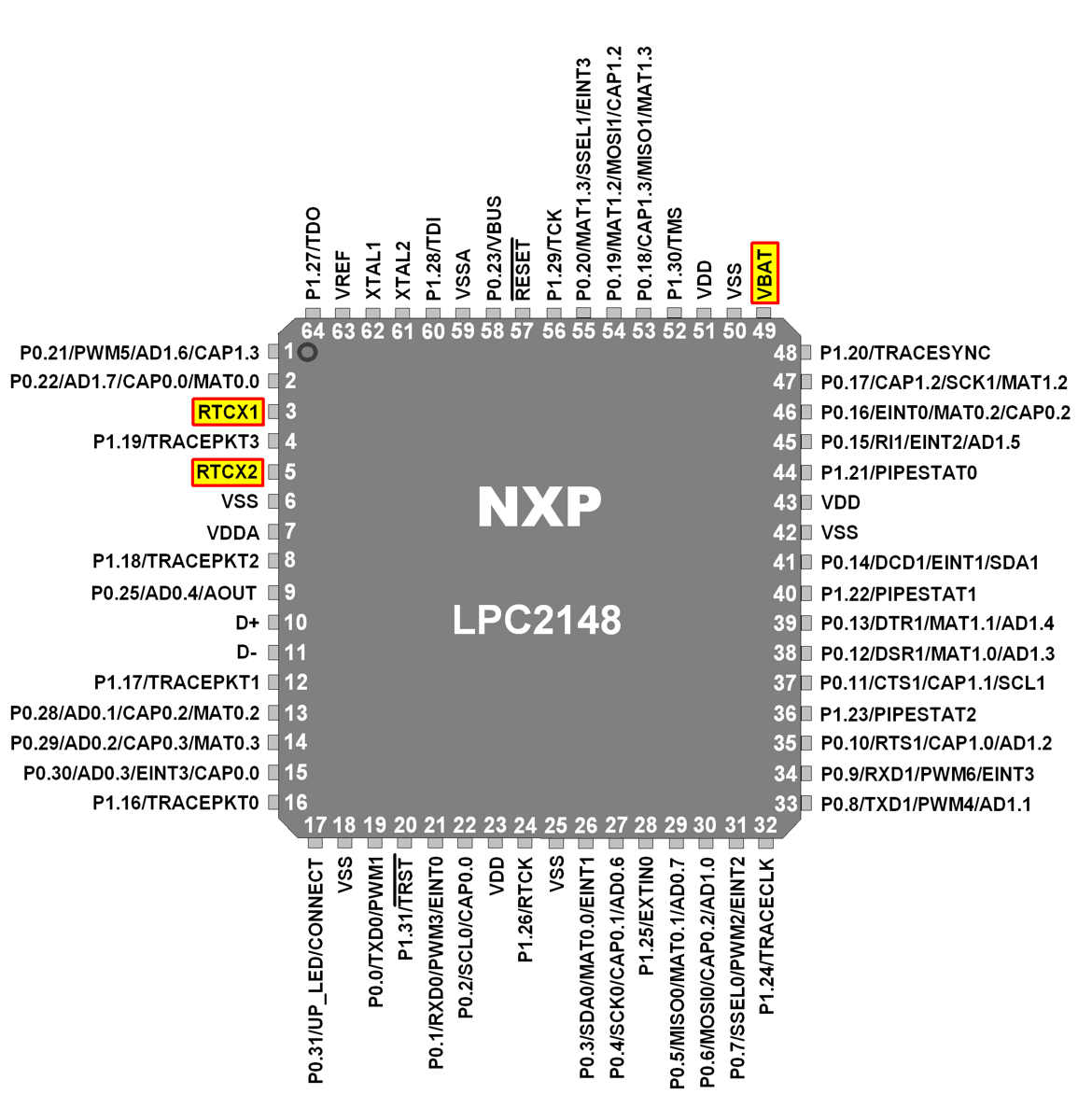
RTCX1 & RTCX1 (RTC Crystal Pins)
These pins are used to connect RTC external crystal. Generally, 32.768 kHz crystal oscillator is connected to these pins.
VBAT (RTC Power pin)
Power to the RTC unit is given through this pin. Either it will be from main system power or from battery backup mechanism.
Now, let’s see RTC Registers that are used to set and control RTC operations.
RTC Registers Configuration
1. ILR (Interrupt Location Register)
- It is an 8-bit register.
- It specifies which blocks are generating an interrupt.
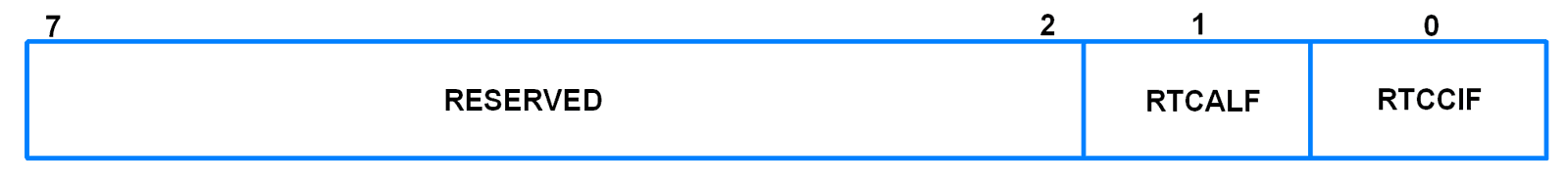
- Bit 0 – RTCCIF
When this bit is 1, it means that the counter increment interrupt block generated an interrupt.
Writing a 1 to this bit clears the counter increment interrupt. Writing a 0 has no effect. - Bit 1 – RTCALF
When this bit is 1, it means that the alarm registers generated an interrupt.
Writing a 1 to this bit clears the alarm interrupt. Writing a 0 has no effect.
2. CTCR (Clock Tick Counter Register)
- It is a 16-bit register.
- It is a read only register.

- It can be reset through the Clock Control Register (CCR).
- It consists of the bits of the clock divide counter.
- Bits 14:1 – Clock Tick Counter
Prior to the seconds counter, the CTC counts 32,768 clocks per second. Due to RTC Prescalar, these 32,768 time increments may not all be of the same duration.
3. CCR (Clock Control Register)
- It is an 8-bit register.
- It controls the operation of the clock divide circuit.

- Bit 0 – CLKEEN (Clock Enable)
0 = Timer counters are disabled. They should be initialized in this condition.
1 = Timer counters are enabled - Bit 1 – CTRST (CTC Reset)
When 1, elements in CTC (Clock Tick Counter) are reset. The elements remain reset until this bit is changed to 0. - Bit 3:2 – CTTEST (Test Enable)
These bits should always be 0 during normal operation. - Bit 4 – CLKSRC
0 = CTC takes clock from Prescalar
1 = CTC takes clock from 32.768 kHz oscillator
Note: It is possible to use both 32.768kHz external oscillator as well as prescaler to run the RTC.
If 32.768 kHz oscillator is used to run the RTC, the RTC maintains the exact time (registers are updated by the 32.768 kHz clock which is powered by the battery) even if the power to the board is cut (only if a 3V battery is connected to the battery pins of the RTC).
If peripheral clock is used to run the RTC, the RTC maintains the register values (registers are not updated since there is no clock source) present at the time of power cut (only if a 3V battery is connected to the battery pins of the RTC).
4. CIIR (Counter Increment Interrupt Register)
- It is an 8-bit register.
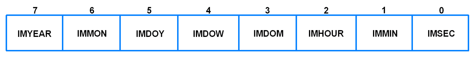
- It provides the option to generate an interrupt every time a counter is incremented.
- This interrupt remains valid until it is cleared by writing a 1 to RTCCIF bit in ILR.
- Bit 0 – IMSEC
When 1, an increment of the Seconds value generates an interrupt. - Bit 1 – IMMIN
When 1, an increment of the Minutes value generates an interrupt. - Bit 2 – IMHOUR
When 1, an increment of the Hours value generates an interrupt. - Bit 3 – IMDOM
When 1, an increment of the Day of Month value generates an interrupt. - Bit 4 – IMDOW
When 1, an increment of the Day of Week value generates an interrupt. - Bit 5 – IMDOY
When 1, an increment of the Day of Year value generates an interrupt. - Bit 6 – IMMON
When 1, an increment of the Month value generates an interrupt. - Bit 7 – IMYEAR
When 1, an increment of the Year value generates an interrupt.
5. AMR (Alarm Mask Register)
- It is an 8-bit register.
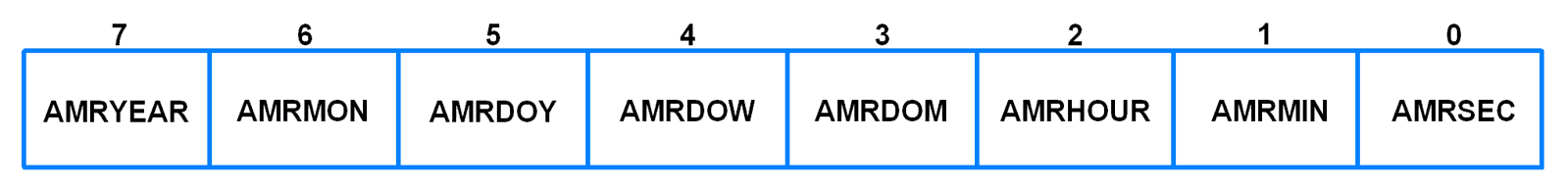
- It allows user to mask any of the alarm registers.
- Writing a 1 to any bit in this register masks the corresponding register.
- For alarm function, every non-masked alarm register must match the corresponding time counter for an interrupt to be generated.
- The interrupt is generated only when the counter comparison first changes from no match to match.
- The interrupt is removed by writing 1 to the RTCALF bit in ILR.
- If all the bits in this register are set, then the alarm is disabled.
- Bit 0 – AMRSEC
When 1, the Seconds value is not compared for alarm. - Bit 1 – AMRMIN
When 1, the Minutes value is not compared for alarm. - Bit 2 – AMRHOUR
When 1, the Hours value is not compared for alarm. - Bit 3 – AMRDOM
When 1, the Day of Month value is not compared for alarm. - Bit 4 – AMRDOW
When 1, the Day of Week value is not compared for alarm. - Bit 5 – AMRDOY
When 1, the Day of Year value is not compared for alarm. - Bit 6 – AMRMON
When 1, the Month value is not compared for alarm. - Bit 7 – AMRYEAR
When 1, the Year value is not compared for alarm.
6. Consolidated Time Registers
- The 3 consolidated time registers together provide an alternative to reading the values of 8 time counter registers.
- These are read only registers.
- These are 32-bit registers.
a) CTIME0 (Consolidated Time Register 0)
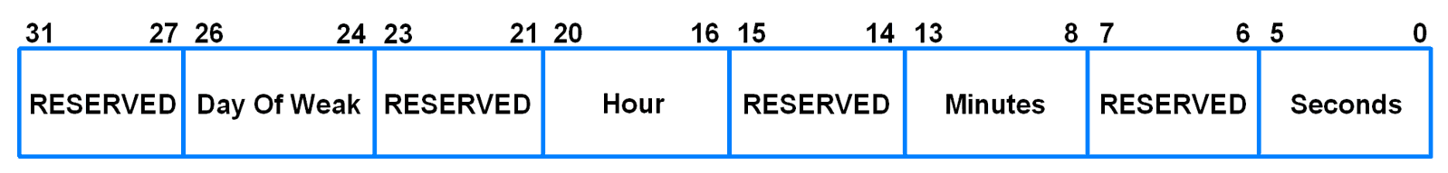
- Bits 5:0 – Seconds
Seconds value in the range of 0 to 59. - Bits 13:8 – Minutes
Minutes value in the range of 0 to 59. - Bits 20:16 – Hours
Hours value in the range of 0 to 23. - Bits 26:24 – Day of Week
Day of Week value in the range of 0 to 6.
b) CTIME1 (Consolidated Time Register 1)
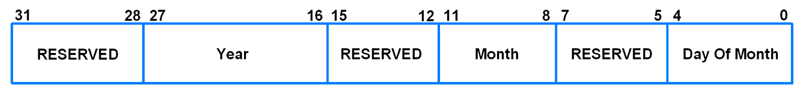
- Bits 4:0 – Day of Month
Day of Month value in the range of 1 to 28, 29, 30 or 31 (depending on the month and whether it is a leap year). - Bits 11:8 – Month
Month value in the range of 1 to 12. - Bits 27:16 – Year
Year value in the range of 0 to 4095.
c) CTIME2 (Consolidated Time Register 2)

- Bits 11:0 – Day of Year
Day of Year value in the range of 1 to 365 (366 for leap years).
7. Time Counter Group
- It consists of 8 counters.
- These can be read/write.
- They are given in the table below.
| Name | Size | Description |
| SEC | 6 | Seconds value in the range of 0 to 59 |
| MIN | 6 | Minutes value in the range of 0 to 59 |
| HOUR | 5 | Hours value in the range of 0 to 23 |
| DOM | 5 | Day of Month value in the range of 1 to 28, 29, 30 or 31 (depending on month and whether it is a leap year) |
| DOW | 3 | Day of Week value in the range of 0 to 6 |
| DOY | 9 | Day of Year value in the range of 1 to 365 (366 for leap years 0 |
| MONTH | 4 | Month value in the range of 1 to 12 |
| YEAR | 12 | Year value in the range of 0 to 4095 |
8. Alarm Register Group
- It consists of 8 counters.
- The values in these registers are compared with the timer counters.
- If all unmasked alarm registers match their corresponding time counters, then an interrupt is generated.
- These registers are given in the table below.
| Name | Size | Description |
| ALSEC | 6 | Alarm value for Seconds |
| ALMIN | 6 | Alarm value for Minutes |
| ALHOUR | 5 | Alarm value for Hours |
| ALDOM | 5 | Alarm value for Day of Month |
| ALDOW | 3 | Alarm value for Day of Week |
| ALDOY | 9 | Alarm value for Day of Year |
| ALMON | 4 | Alarm value for Month |
| ALYEAR | 12 | Alarm value for Year |
9. PREINT (Prescaler Integer Register)
- When PCLK acts as the clock source for RTC, then, this prescaler allows generation of 32.768 kHz reference clock from any PCLK greater than 65.536 kHz (2 * 32.768).
- This allows RTC to run at proper rate irrespective of the PCLK.
- PREINT is the integer portion of the prescale value.
- PREINT = int (PCLK/32768) – 1
- PREINT must be greater than or equal to 1.

- Bits 12:0 – Prescale Integer
Contains the integer value of the RTC prescaler.
10. PREFRAC (Prescaler Fraction Register)
- This is the fractional part of the prescale value.
- PREFRAC = PCLK – ((PREINT+1) * 32768)

- Bits 14:0 - Prescale Fraction
Contains the fraction value of the RTC prescaler.
Let’s take example for prescale register values
For PCLK = 15 MHz
PREINT = int (15000000/32768) – 1 = 457 – 1 = 456 (0x1C8)
PREFRAC = 15000000 – ((456+1) * 32768) = 15000000 – 14974976 = 25024 (0x61C0)
Note: Leap Year
RTC considers all the years that are divisible by 4 as a leap year. This algorithm is accurate from the year 1901 to 2099, but fails for the year 2100 which is not a leap year.
Example
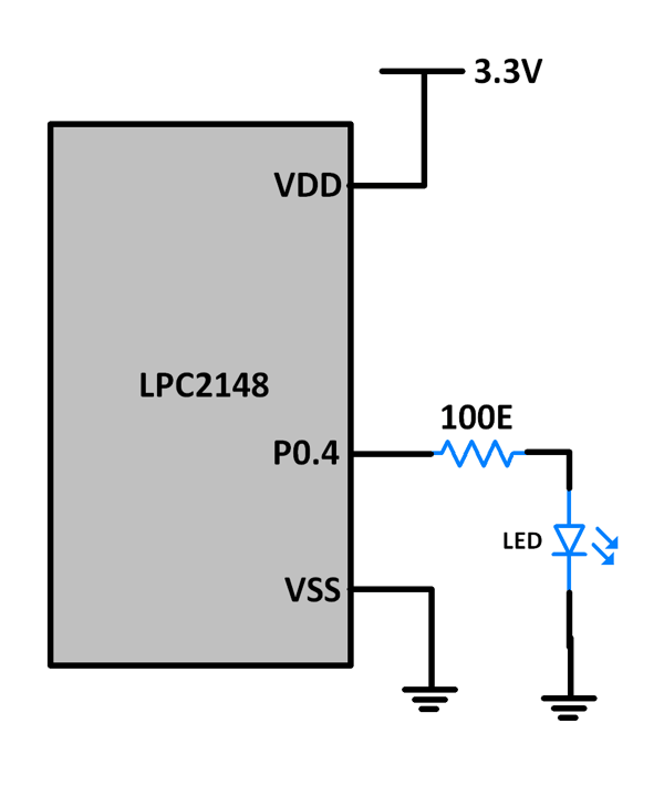
Let’s write a program to set RTC time and generate alarm at desired time. UART0 is used to display time and alarm event on PC terminal. An LED is also used as an indicator of the alarm. The LED is blinked for 6 seconds when the alarm is turned on.
We will see programs for RTC run using 32.768 kHz crystal as well as using prescaler.
Program for RTC run using Prescaler
/*
  RTC in LPC2148(ARM7)
  http://www.electronicwings.com/arm7/lpc2148-rtc-real-time-clock
*/

#include <lpc214x.h>
#include <stdint.h>
#include <stdio.h>
#include "UART0.h"

uint8_t alarm, flag;

__irq void RTC_ISR(void)
{
	if (ILR & 0x01)
	{
		flag = 1;
		ILR = ILR | 0x01;
	}
	if (ILR & 0x02)
	{
		alarm = 1;
		ILR = ILR | 0x02;
	}
	VICVectAddr = 0;
}

typedef struct
{
	uint8_t seconds;
	uint8_t minutes;
	uint8_t hours;
	uint8_t day_of_month;
	uint8_t day_of_week;
	uint16_t day_of_year;
	uint8_t month;
	uint16_t year;
}RTC_Time;

void RTC_Set_Time( RTC_Time Set_Time)
{
	SEC = Set_Time.seconds;
	MIN = Set_Time.minutes;
	HOUR = Set_Time.hours;
	DOM = Set_Time.day_of_month;
	DOW = Set_Time.day_of_week;
	DOY = Set_Time.day_of_year;
	MONTH = Set_Time.month;
	YEAR = Set_Time.year;
}

void RTC_Set_Alarm_Time( RTC_Time Alarm_Time)
{
	ALSEC = Alarm_Time.seconds;
	ALMIN = Alarm_Time.minutes;
	ALHOUR = Alarm_Time.hours;
	ALDOM = Alarm_Time.day_of_month;
	ALDOW = Alarm_Time.day_of_week;
	ALDOY = Alarm_Time.day_of_year;
	ALMON = Alarm_Time.month;
	ALYEAR = Alarm_Time.year;
}

RTC_Time RTC_Get_Time(void)
{
	RTC_Time time;
	time.seconds = SEC;
	time.minutes = MIN;
	time.hours = HOUR;
	time.day_of_month = DOM;
	time.day_of_week = DOW;
	time.day_of_year = DOY;
	time.month = MONTH;
	time.year = YEAR;
	return time;
}

int main(void)
{
	/* Setting Time + Alarm */
	RTC_Time set_time, alarm_time, current_time;
	char timestr[30], datestr[30];
	alarm = 0;
	flag = 0;
	IO0DIR = 0x00000010; /* P0.4 as output pin for LED */
	UART0_init();
	ILR = 0x0; 			/* No RTC interrupts */
	CCR = 0x02; 		/* Reset Clock Tick Counter */
	CCR = 0x00;
	CIIR = 0x00; 		/* No interrupts */
	AMR = 0x00; 		/* Alarm registers not masked */
	PREINT = 0x01C8; 	/* For 15MHz Fpclk, PREINT value */
	PREFRAC = 0x61C0; 	/* For 15MHz Fpclk, PREFRAC value */
	VICVectAddr0 = (unsigned) RTC_ISR;
	VICVectCntl0 = 0x0000002D;
	VICIntEnable = 0x00002000;
	VICIntSelect = 0x00000000;
	set_time.seconds = 00;
	set_time.minutes = 25;
	set_time.hours = 11;
	set_time.day_of_month = 6;
	set_time.day_of_week = 5;
	set_time.day_of_year = 279;
	set_time.month = 10;
	set_time.year = 2017;
	RTC_Set_Time(set_time);
	CIIR = 0x01; 		/* Seconds value increment interrupt */
	alarm_time.seconds = 15;
	alarm_time.minutes = 25;
	alarm_time.hours = 11;
	alarm_time.day_of_month = 6;
	alarm_time.day_of_week = 5;
	alarm_time.day_of_year = 279;
	alarm_time.month = 10;
	alarm_time.year = 2017;
	RTC_Set_Alarm_Time(alarm_time);
	CCR = 0x01; 		/* Clock Enable */
	ILR = 0x03; 		/* RTC interrupts enabled */
	IO0CLR = 0x00000010;
	/* Set the Time and Alarm once using above code lines */
	/* Once the time and alarm is set, comment out the above code lines and uncomment the code lines for "Only RTC Read" and program the device */
	/* If this is not done, the time will be set repeatedly to same value whenever the device is reset or powered */


	/* Only RTC Read */
//	RTC_Time current_time;
//	char timestr[30], datestr[30];
//	alarm = 0;
//	flag = 0;
//	IO0DIR = 0x00000010; 	/* P0.4 as output pin for LED */
//	UART0_init();
//	CCR = 0x02; 			/* Reset Clock Tick Counter */
//	AMR = 0x00; 			/* Alarm registers not masked */
//	PREINT = 0x01C8; 		/* For 15MHz Fpclk, PREINT value */
//	PREFRAC = 0x61C0; 		/* For 15MHz Fpclk, PREFRAC value */
//	VICVectAddr0 = (unsigned) RTC_ISR;
//	VICVectCntl0 = 0x0000002D;
//	VICIntEnable = 0x00002000;
//	VICIntSelect = 0x00000000;
//	CCR = 0x01; 			/* Clock Enable */
//	ILR = 0x03; 			/* RTC interrupts enabled */
//	IO0CLR = 0x00000010;

	/* Code lines below are common for "Setting time + Alarm" as well as "Only RTC Read" */
	while(1)
	{
		if(alarm == 1)
		{
			current_time = RTC_Get_Time();
			sprintf(timestr,"Alarm!!!: %d:%d:%d \r\n",current_time.hours,current_time.minutes,current_time.seconds);
			UART0_SendString(timestr);
			uint8_t i;
			for(i=0;i<10;i++)
			{
				IO0SET = 0x00000010;
				delay_ms(300);
				IO0CLR = 0x00000010;
				delay_ms(300);
			}
			alarm = 0;
		}
		if (flag == 1)
		{
			current_time = RTC_Get_Time();
			sprintf(timestr,"Time: %d:%d:%d ",current_time.hours,current_time.minutes,current_time.seconds);
			sprintf(datestr,"Date: %d/%d/%d \r\n",current_time.day_of_month,current_time.month,current_time.year);
			UART0_SendString(timestr);
			UART0_SendString(datestr);
			flag = 0;
		}
	}
}
Program for RTC run using 32.768kHz crystal
/*
  RTC in LPC2148(ARM7)
  http://www.electronicwings.com/arm7/lpc2148-rtc-real-time-clock
*/

#include <lpc214x.h>
#include <stdint.h>
#include <stdio.h>
#include "UART0.h"

uint8_t alarm, flag;

__irq void RTC_ISR(void)
{
	if (ILR & 0x01)
	{
		flag = 1;
		ILR = ILR | 0x01;
	}
	if (ILR & 0x02)
	{
		alarm = 1;
		ILR = ILR | 0x02;
	}
	VICVectAddr = 0;
}

typedef struct
{
	uint8_t seconds;
	uint8_t minutes;
	uint8_t hours;
	uint8_t day_of_month;
	uint8_t day_of_week;
	uint16_t day_of_year;
	uint8_t month;
	uint16_t year;
}RTC_Time;

void RTC_Set_Time( RTC_Time Set_Time)
{
	SEC = Set_Time.seconds;
	MIN = Set_Time.minutes;
	HOUR = Set_Time.hours;
	DOM = Set_Time.day_of_month;
	DOW = Set_Time.day_of_week;
	DOY = Set_Time.day_of_year;
	MONTH = Set_Time.month;
	YEAR = Set_Time.year;
}

void RTC_Set_Alarm_Time( RTC_Time Alarm_Time)
{
	ALSEC = Alarm_Time.seconds;
	ALMIN = Alarm_Time.minutes;
	ALHOUR = Alarm_Time.hours;
	ALDOM = Alarm_Time.day_of_month;
	ALDOW = Alarm_Time.day_of_week;
	ALDOY = Alarm_Time.day_of_year;
	ALMON = Alarm_Time.month;
	ALYEAR = Alarm_Time.year;
}

RTC_Time RTC_Get_Time(void)
{
	RTC_Time time;
	time.seconds = SEC;
	time.minutes = MIN;
	time.hours = HOUR;
	time.day_of_month = DOM;
	time.day_of_week = DOW;
	time.day_of_year = DOY;
	time.month = MONTH;
	time.year = YEAR;
	return time;
}

int main(void)
{
	/* Setting Time + Alarm */
	RTC_Time set_time, alarm_time, current_time;
	char timestr[30], datestr[30];
	alarm = 0;
	flag = 0;
	IO0DIR = 0x00000010; /* P0.4 as output pin for LED */
	UART0_init();
	PCONP = (PCONP | (1<<9)); /* PCRTC = 1 */
	/* The RTC registers cannot be written to unless we make PCRTC = 1 */
	ILR = 0x0; /* No RTC interrupts */
	CCR = 0x12; /* 32.768kHz clock and Reset Clock Tick Counter */
	CCR = 0x10;
	CIIR = 0x00; /* No interrupts */
	AMR = 0x00; /* Alarm registers not masked */
	VICVectAddr0 = (unsigned) RTC_ISR;
	VICVectCntl0 = 0x0000002D;
	VICIntEnable = 0x00002000;
	VICIntSelect = 0x00000000;
	set_time.seconds = 00;
	set_time.minutes = 25;
	set_time.hours = 11;
	set_time.day_of_month = 6;
	set_time.day_of_week = 5;
	set_time.day_of_year = 279;
	set_time.month = 10;
	set_time.year = 2017;
	RTC_Set_Time(set_time);
	CIIR = 0x01; /* Seconds value increment interrupt */
	alarm_time.seconds = 15;
	alarm_time.minutes = 25;
	alarm_time.hours = 11;
	alarm_time.day_of_month = 6;
	alarm_time.day_of_week = 5;
	alarm_time.day_of_year = 279;
	alarm_time.month = 10;
	alarm_time.year = 2017;
	RTC_Set_Alarm_Time(alarm_time);
	CCR = 0x11; /* 32.768kHz clock and clock Enable */
	ILR = 0x03; /* RTC interrupts enabled */
	IO0CLR = 0x00000010;
	/* Set the Time and Alarm once using above code lines */
	/* Once the time and alarm is set, comment out the above code lines and uncomment the code lines for "Only RTC Read" and program the device */
	/* If this is not done, the time will be set repeatedly to same value whenever the device is reset or powered */


	/* Only RTC Read */
//	RTC_Time current_time;
//	char timestr[30], datestr[30];
//	alarm = 0;
//	flag = 0;
//	IO0DIR = 0x00000010; /* P0.4 as output pin for LED */
//	UART0_init();
//	AMR = 0x00; /* Alarm registers not masked */
//	CCR = 0x10;
//	VICVectAddr0 = (unsigned) RTC_ISR;
//	VICVectCntl0 = 0x0000002D;
//	VICIntEnable = 0x00002000;
//	VICIntSelect = 0x00000000;
//	CCR = 0x11; /* 32.768kHz clock and clock enable */
//	ILR = 0x03; /* RTC interrupts enabled */
//	IO0CLR = 0x00000010;

    /* Code lines below are common for "Setting time + Alarm" as well as "Only RTC Read" */
	while(1)
	{
		if(alarm == 1)
		{
			current_time = RTC_Get_Time();
			sprintf(timestr,"Alarm!!!: %d:%d:%d \r\n",current_time.hours,current_time.minutes,current_time.seconds);
			UART0_SendString(timestr);
			uint8_t i;
			for(i=0;i<10;i++)
			{
				IO0SET = 0x00000010;
				delay_ms(300);
				IO0CLR = 0x00000010;
				delay_ms(300);
			}
			alarm = 0;
		}
		if (flag == 1)
		{
			current_time = RTC_Get_Time();
			sprintf(timestr,"Time: %d:%d:%d ",current_time.hours,current_time.minutes,current_time.seconds);
			sprintf(datestr,"Date: %d/%d/%d \r\n",current_time.day_of_month,current_time.month,current_time.year);
			UART0_SendString(timestr);
			UART0_SendString(datestr);
			flag = 0;
		}
	}
}
Video
Components Used |
||
|---|---|---|
| ARM7 LPC2148 ARM7 LPC2148 |
X 1 | |
| Breadboard Breadboard |
X 1 | |
| LED 5mm LED 5mm |
X 1 | |