Introduction to DAC
Digital to Analog Converter (DAC) are mostly used to generate analog signals (e.g. sine wave, triangular wave etc.) from digital values.
- LPC2148 has 10-bit DAC with resistor string architecture. It also works in Power down mode.
- LPC2148 has Analog output pin (AOUT) on chip, where we can get digital value in the form of Analog output voltage.
- The Analog voltage on AOUT pin is calculated as ((VALUE/1024) * VREF). Hence, we can change voltage by changing VALUE(10-bit digital value) field in DACR (DAC Register).
- e.g. if we set VALUE = 512,
then, we can get analog voltage on AOUT pin as ((512/1024) * VREF) = VREF/2.
LPC2148 DAC Pins
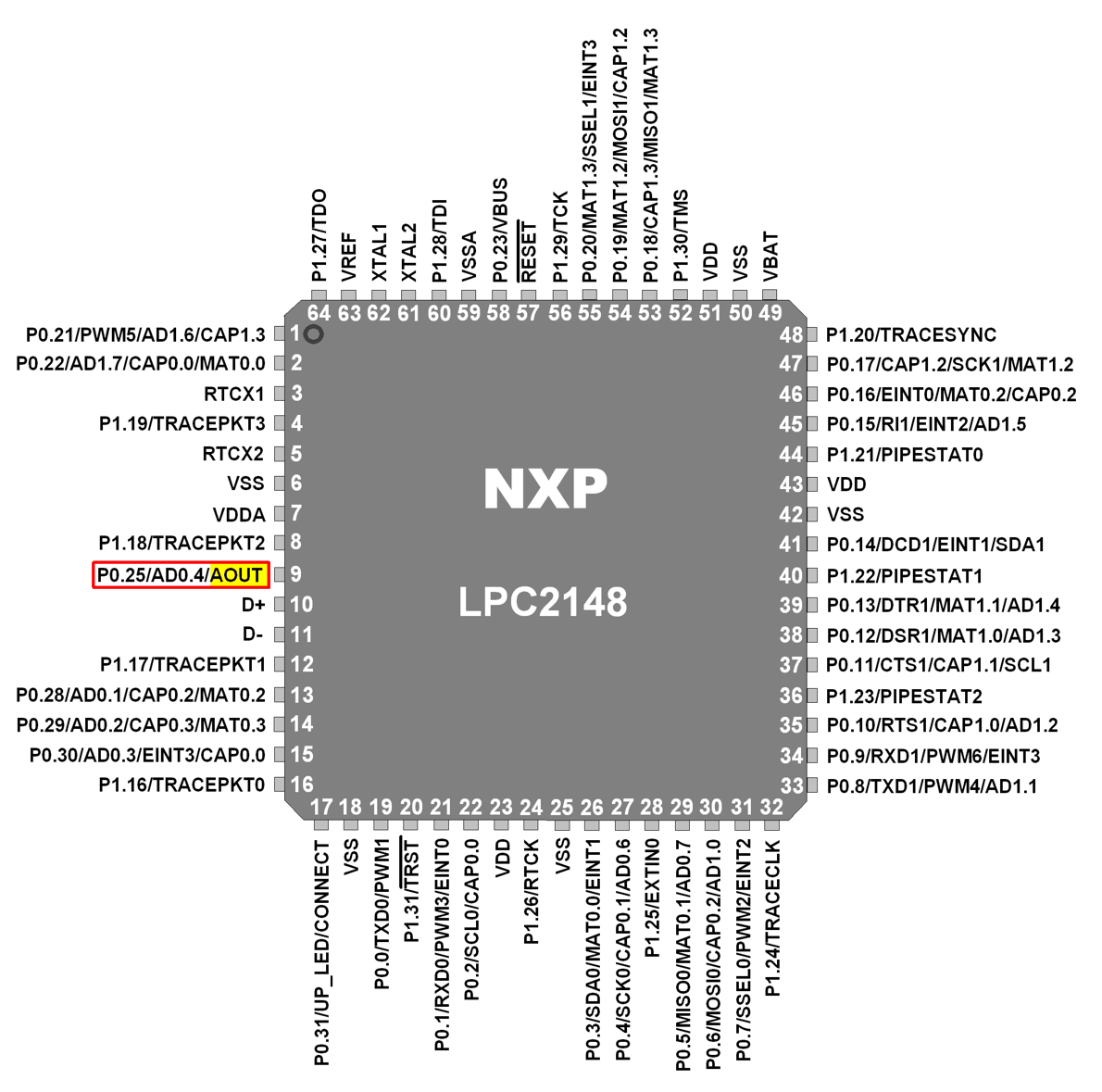
AOUT (Analog Output)
This is Analog Output pin of LPC2148 DAC peripheral where we can get Analog output voltage from digital value.
VREF (Voltage Reference)
Provides Voltage Reference for DAC.
VDDA& VSSA (Analog Power and Ground)
These are the power and ground pins for DAC. These should be same as VDD& VSS.
DAC Register Configuration
Let’s see the Register used for DAC
DACR (DAC Register)
- DACR is a 32-bit register.
- It is a read-write register.

- Bit 5:0 – RESERVED
- Bits 15:6 – VALUE
This field contains the 10-bit digital value that is to be converted in to Analog voltage. We can get Analog output voltage on AOUT pin and it is calculated with the formula (VALUE/1024) * VREF. - Bit 16 – BIAS
0 = Maximum settling time of 1µsec and maximum current is 700µA
1 = Settling time of 2.5µsec and maximum current is 350µA
Note that, the settling times are valid for a capacitance load on the AOUT pin not exceeding 100 pF. A load impedance value greater than that value will cause settling time longer than the specified time. - Bit 31:17 – RESERVED
Programming Steps
- First, configure P0.25/AOUT pin as DAC output using PINSEL Register.
- Then set settling time using BIAS bit in DACR Register.
- Now write 10-bit value (which we want to convert into analog form) in VALUE field of DACR Register.
Example
Let’s write a simple program for LPC2148 DAC.
Here, we will load the DACR value with various values to generate a sine wave, triangular wave, sawtooth wave, square wave and DC wave.
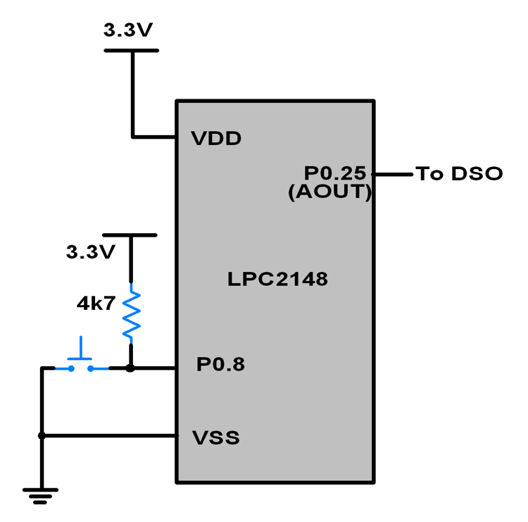
4 switches are used as inputs on P0.8 (for sine wave), P0.9 (for triangular wave), P0.10 (for sawtooth wave), and P0.11 (for square wave) pins.
These pins are connected to 3.3 V through pull-up resistors. The switches are connected as shown below. Only switch for P0.8 is shown in the figure. Switches are connected in a similar manner to the other 3 pins as well.
If we connect the DAC output pin P0.25 to an oscilloscope, we can observe the different waves.
Interfacing Diagram
Program for LPC2148 DAC
/*
  DAC in LPC2148(ARM7)
  http://www.electronicwings.com/arm7/lpc2148-dac-digital-to-analog-converter
*/

#include <lpc214x.h>
#include <stdint.h>


void delay_ms(uint16_t j)
{
    uint16_t x,i;
	for(i=0;i<j;i++)
	{
    for(x=0; x<6000; x++);    /* loop to generate 1 milisecond delay with Cclk = 60MHz */
	}
}

int main (void)
{
  uint16_t value;
	uint8_t i;
	i = 0;
	PINSEL1 = 0x00080000;	/* P0.25 as DAC output */
	IO0DIR = ( IO0DIR & 0xFFFFF0FF ); /* Input pins for switch. P0.8 sine, P0.9 triangular, P0.10 sawtooth, P0.11 square */
	uint16_t sin_wave[42] = { 512,591,665,742,808,873,926,968,998,1017,1023,1017,998,968,926,873,808,742,665,591,512,
														436,359,282,216,211,151,97,55,25,6,0,6,25,55,97,151,211,216,282,359,436 };
	while(1)
	{
		if ( !(IO0PIN & (1<<8)) )	/* If switch for sine wave is pressed */
		{
				while(i !=42)
				{
					value = sin_wave[i];
					DACR = ( (1<<16) | (value<<6) );
					delay_ms(1);
					i++;
				}
				i = 0;
		}
		else if ( !(IO0PIN & (1<<9)) )	/* If switch for triangular wave is pressed */
		{
				value = 0;
				while ( value != 1023 )
				{
					DACR = ( (1<<16) | (value<<6) );
					value++;
				}
				while ( value != 0 )
				{
					DACR = ( (1<<16) | (value<<6) );
					value--;
				}
		}
		else if ( !(IO0PIN & (1<<10)) )	/* If switch for sawtooth wave is pressed */
		{

				value = 0;
				while ( value != 1023 )
				{
					DACR = ( (1<<16) | (value<<6) );
					value++;
				}
		}
		else if ( !(IO0PIN & (1<<11)) )	/* If switch for square wave is pressed */
		{
				value = 1023;
				DACR = ( (1<<16) | (value<<6) );
				delay_ms(100);
				value = 0;
				DACR = ( (1<<16) | (value<<6) );
				delay_ms(100);
		}
		else	/* If no switch is pressed, 3.3V DC */
		{
			value = 1023;
			DACR = ( (1<<16) | (value<<6) );
		}
	}
}
Video
Components Used |
||
|---|---|---|
| ARM7 LPC2148 ARM7 LPC2148 |
X 1 | |
| Mini Push Button Switch - 5-6mm Mini Push Button Switch - 5-6mm |
X 1 | |
| Breadboard Breadboard |
X 1 | |