Overview of MPU6050 Sensor
- The MPU6050 sensor module is an integrated 6-axis Motion tracking device.
- It has a 3-axis Gyroscope, 3-axis Accelerometer, Digital Motion Processor, and a Temperature sensor, all in a single IC.
- It can accept inputs from other sensors like a 3-axis magnetometer or pressure sensor using its Auxiliary I2C bus.
- If an external 3-axis magnetometer is connected, it can provide complete 9-axis Motion Fusion output.
- A microcontroller can communicate with this module using the I2C communication protocol. Various parameters can be found by reading values from addresses of certain registers using I2C communication.
- Gyroscope and accelerometer reading along X, Y, and Z axes are available in 2’s complement form.
- Gyroscope readings are in degrees per second (dps) unit; Accelerometer readings are in g unit.
For more information about MPU6050 Sensor Module and how to use it, refer the topic MPU6050 Sensor Module in the sensors and modules section.
To interface MPU6050 using Raspberry Pi, we should ensure that the I2C protocol on Raspberry Pi is turned on. So before going for interfacing MPU6050 with Raspberry Pi, we need to make some I2C configurations on Raspberry Pi which you can refer Raspberry Pi I2C.
After configuring I2C on Raspberry Pi, let’s interface Raspberry Pi with MPU6050.
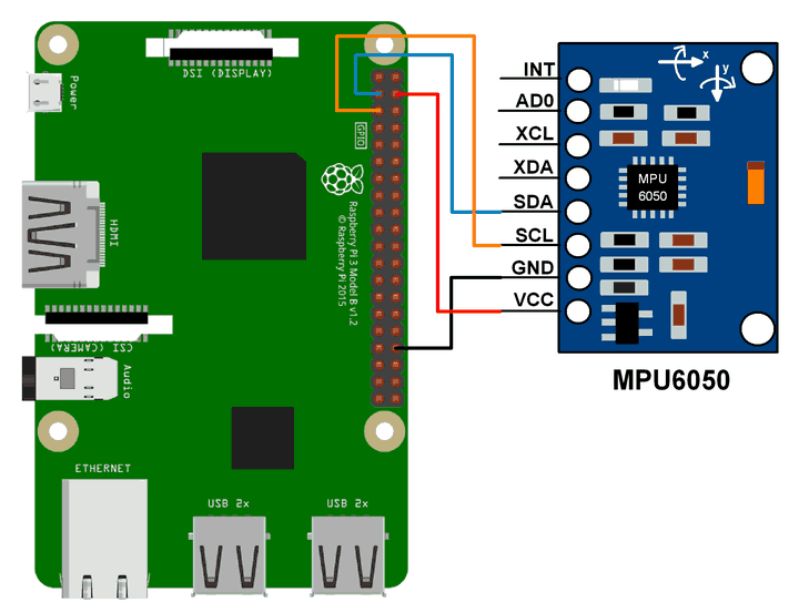
Connection Diagram of MPU6050 with Raspberry Pi
MPU6050 Example using Raspberry Pi
Here, we will interface the MPU6050 module with Raspberry Pi to read Gyroscope and Accelerometer values and print them.
We can interface the MPU6050 module with Raspberry Pi using Python and C language. We will display the value of the Accelerometer and Gyroscope on the terminal which are read from the MPU6050 module.
For frequently used Python based I2C function on Raspberry Pi, you can refer Python based I2C functions for Raspberry Pi.
MPU6050 Code for Raspberry Pi using Python
'''
        Read Gyro and Accelerometer by Interfacing Raspberry Pi with MPU6050 using Python
	http://www.electronicwings.com
'''
import smbus					#import SMBus module of I2C
from time import sleep          #import

#some MPU6050 Registers and their Address
PWR_MGMT_1   = 0x6B
SMPLRT_DIV   = 0x19
CONFIG       = 0x1A
GYRO_CONFIG  = 0x1B
INT_ENABLE   = 0x38
ACCEL_XOUT_H = 0x3B
ACCEL_YOUT_H = 0x3D
ACCEL_ZOUT_H = 0x3F
GYRO_XOUT_H  = 0x43
GYRO_YOUT_H  = 0x45
GYRO_ZOUT_H  = 0x47


def MPU_Init():
	#write to sample rate register
	bus.write_byte_data(Device_Address, SMPLRT_DIV, 7)

	#Write to power management register
	bus.write_byte_data(Device_Address, PWR_MGMT_1, 1)

	#Write to Configuration register
	bus.write_byte_data(Device_Address, CONFIG, 0)

	#Write to Gyro configuration register
	bus.write_byte_data(Device_Address, GYRO_CONFIG, 24)

	#Write to interrupt enable register
	bus.write_byte_data(Device_Address, INT_ENABLE, 1)

def read_raw_data(addr):
	#Accelero and Gyro value are 16-bit
        high = bus.read_byte_data(Device_Address, addr)
        low = bus.read_byte_data(Device_Address, addr+1)

        #concatenate higher and lower value
        value = ((high << 8) | low)

        #to get signed value from mpu6050
        if(value > 32768):
                value = value - 65536
        return value


bus = smbus.SMBus(1) 	# or bus = smbus.SMBus(0) for older version boards
Device_Address = 0x68   # MPU6050 device address

MPU_Init()

print (" Reading Data of Gyroscope and Accelerometer")

while True:

	#Read Accelerometer raw value
	acc_x = read_raw_data(ACCEL_XOUT_H)
	acc_y = read_raw_data(ACCEL_YOUT_H)
	acc_z = read_raw_data(ACCEL_ZOUT_H)

	#Read Gyroscope raw value
	gyro_x = read_raw_data(GYRO_XOUT_H)
	gyro_y = read_raw_data(GYRO_YOUT_H)
	gyro_z = read_raw_data(GYRO_ZOUT_H)

	#Full scale range +/- 250 degree/C as per sensitivity scale factor
	Ax = acc_x/16384.0
	Ay = acc_y/16384.0
	Az = acc_z/16384.0

	Gx = gyro_x/131.0
	Gy = gyro_y/131.0
	Gz = gyro_z/131.0


	print ("Gx=%.2f" %Gx, u'\u00b0'+ "/s", "\tGy=%.2f" %Gy, u'\u00b0'+ "/s", "\tGz=%.2f" %Gz, u'\u00b0'+ "/s", "\tAx=%.2f g" %Ax, "\tAy=%.2f g" %Ay, "\tAz=%.2f g" %Az)
	sleep(1)
MPU6050 Code for Raspberry Pi using C (WiringPi Library)
Here, we are using the WiringPi C library to read data from the MPU6050 module.
/*
	MPU6050 Interfacing with Raspberry Pi
	http://www.electronicwings.com
*/

#include <wiringPiI2C.h>
#include <stdlib.h>
#include <stdio.h>
#include <wiringPi.h>

#define Device_Address 0x68	/*Device Address/Identifier for MPU6050*/

#define PWR_MGMT_1   0x6B
#define SMPLRT_DIV   0x19
#define CONFIG       0x1A
#define GYRO_CONFIG  0x1B
#define INT_ENABLE   0x38
#define ACCEL_XOUT_H 0x3B
#define ACCEL_YOUT_H 0x3D
#define ACCEL_ZOUT_H 0x3F
#define GYRO_XOUT_H  0x43
#define GYRO_YOUT_H  0x45
#define GYRO_ZOUT_H  0x47

int fd;

void MPU6050_Init(){

	wiringPiI2CWriteReg8 (fd, SMPLRT_DIV, 0x07);	/* Write to sample rate register */
	wiringPiI2CWriteReg8 (fd, PWR_MGMT_1, 0x01);	/* Write to power management register */
	wiringPiI2CWriteReg8 (fd, CONFIG, 0);		/* Write to Configuration register */
	wiringPiI2CWriteReg8 (fd, GYRO_CONFIG, 24);	/* Write to Gyro Configuration register */
	wiringPiI2CWriteReg8 (fd, INT_ENABLE, 0x01);	/*Write to interrupt enable register */

	}
short read_raw_data(int addr){
	short high_byte,low_byte,value;
	high_byte = wiringPiI2CReadReg8(fd, addr);
	low_byte = wiringPiI2CReadReg8(fd, addr+1);
	value = (high_byte << 8) | low_byte;
	return value;
}

void ms_delay(int val){
	int i,j;
	for(i=0;i<=val;i++)
		for(j=0;j<1200;j++);
}

int main(){

	float Acc_x,Acc_y,Acc_z;
	float Gyro_x,Gyro_y,Gyro_z;
	float Ax=0, Ay=0, Az=0;
	float Gx=0, Gy=0, Gz=0;
	fd = wiringPiI2CSetup(Device_Address);   /*Initializes I2C with device Address*/
	MPU6050_Init();		                 /* Initializes MPU6050 */

	while(1)
	{
		/*Read raw value of Accelerometer and gyroscope from MPU6050*/
		Acc_x = read_raw_data(ACCEL_XOUT_H);
		Acc_y = read_raw_data(ACCEL_YOUT_H);
		Acc_z = read_raw_data(ACCEL_ZOUT_H);

		Gyro_x = read_raw_data(GYRO_XOUT_H);
		Gyro_y = read_raw_data(GYRO_YOUT_H);
		Gyro_z = read_raw_data(GYRO_ZOUT_H);

		/* Divide raw value by sensitivity scale factor */
		Ax = Acc_x/16384.0;
		Ay = Acc_y/16384.0;
		Az = Acc_z/16384.0;

		Gx = Gyro_x/131;
		Gy = Gyro_y/131;
		Gz = Gyro_z/131;

		printf("\n Gx=%.3f °/s\tGy=%.3f °/s\tGz=%.3f °/s\tAx=%.3f g\tAy=%.3f g\tAz=%.3f g\n",Gx,Gy,Gz,Ax,Ay,Az);
		delay(500);

	}
	return 0;
}
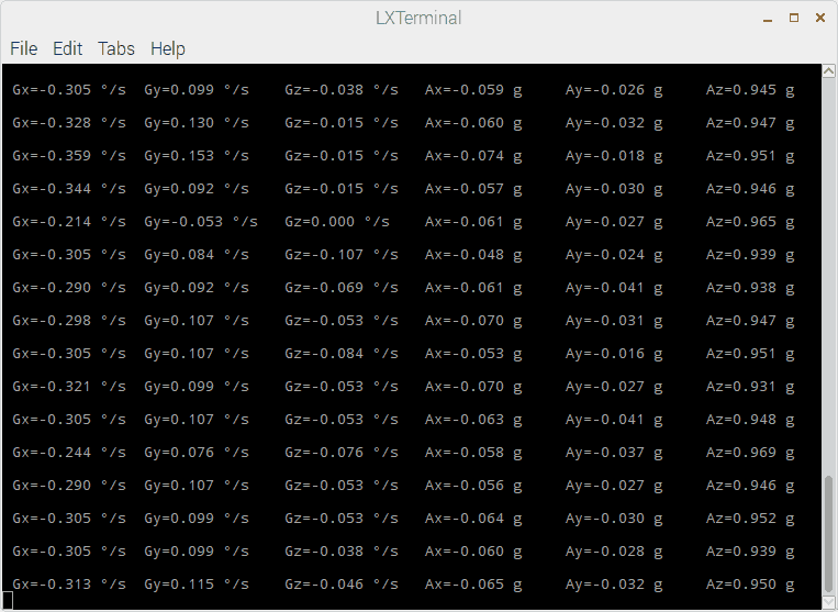
MPU6050 Output
The output window will show all values mentioned below
Gx = Gyro X-axis data in degree/seconds
Gy = Gyro Y-axis data in degree/seconds
Gz = Gyro Z-axis data in degree/seconds
Ax = Accelerometer X-axis data in g
Ay = Accelerometer Y-axis data in g
Az = Accelerometer Z-axis data in g
Components Used |
||
|---|---|---|
| MPU6050 Gyroscope and Accelerometer MPU6050 (Gyroscope + Accelerometer + Temperature) is a combination of 3-axis Gyroscope, 3-axis Accelerometer and Temperature sensor with on-chip Digital Motion Processor (DMP). It is used in mobile devices, motion enabled games, 3D mice, Gesture (motion command) technology etc |
X 1 | |
| Raspberry Pi 4B Raspberry Pi 4BRaspberry Pi 4B |
X 1 | |
| Raspberry Pi Zero Raspberry Pi Zero |
X 1 | |