Introduction to UART
UART (Universal Asynchronous Receiver/Transmitter) is a serial communication protocol in which data is transferred serially i.e. bit by bit. Asynchronous serial communication is widely used for byte oriented transmission. In Asynchronous serial communication, a byte of data is transferred at a time.
UART serial communication protocol uses a defined frame structure for their data bytes. Frame structure in Asynchronous communication consists:
- START bit: It is a bit with which indicates that serial communication has started and it is always low.
- Data bits packet: Data bits can be packets of 5 to 9 bits. Normally we use 8-bit data packet, which is always sent after the START bit.
- STOP bit: This usually is one or two bits in length. It is sent after data bits packet to indicate the end of frame. Stop bit is always logic high.
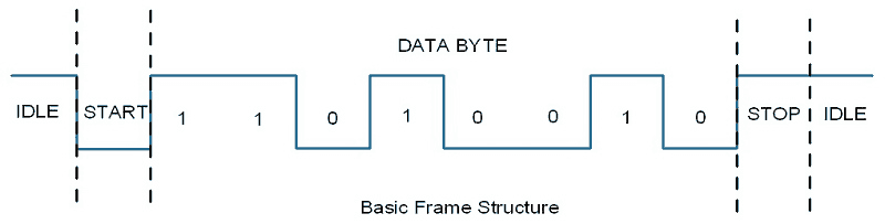
Usually, an asynchronous serial communication frame consists of a START bit (1 bit) followed by a data byte (8 bits) and then a STOP bit (1 bit), which forms a 10-bit frame as shown in the figure above. The frame can also consist of 2 STOP bits instead of a single bit, and there can also be a PARITY bit after the STOP bit.
Raspberry Pi UART
Raspberry Pi has two in-built UART which are as follows:
- PL011 UART
- mini UART
PL011 UART is an ARM based UART. This UART has better throughput than mini UART.
In Raspberry Pi 3, mini UART is used for Linux console output whereas PL011 is connected to the On-board Bluetooth module.
And in the other versions of Raspberry Pi, PL011 is used for Linux console output.
Mini UART uses the frequency which is linked to the core frequency of GPU. So as the GPU core frequency changes, the frequency of UART will also change which in turn will change the baud rate for UART. This makes the mini UART unstable which may lead to data loss or corruption. To make mini UART stable, fix the core frequency. mini UART doesn’t have parity support.
The PL011 is a stable and high performance UART. For better and effective communication use PL011 UART instead of mini UART.
It is recommended to enable the UART of Raspberry Pi for serial communication. Otherwise, we are not able to communicate serially as UART ports are used for Linux console output and Bluetooth module.
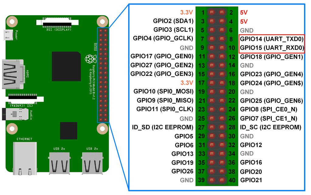
Raspberry Pi 3 UART Pins
Configure UART on Raspberry Pi
In Raspberry Pi, enter following command in Terminal window to enable UART,
sudo raspi-configSelect -> Interfacing Options
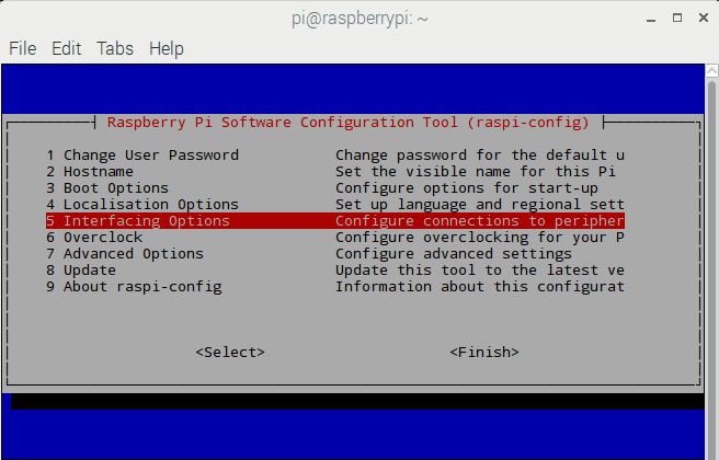
After selecting Interfacing option, select Serial option to enable UART
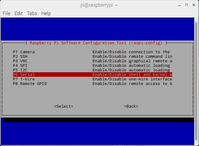
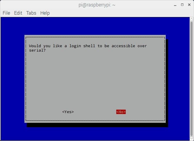
Then it will ask for login shell to be accessible over Serial, select No shown as follows.
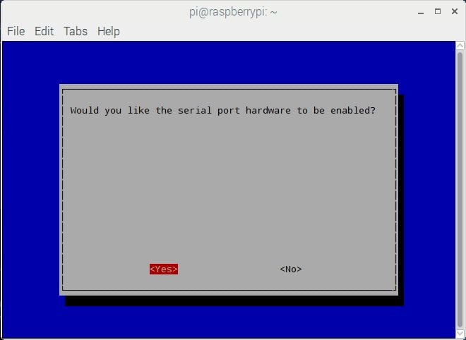
At the end, it will ask for enabling Hardware Serial port, select Yes,
Finally, our UART is enabled for Serial Communication on RX and TX pin of Raspberry Pi 3.
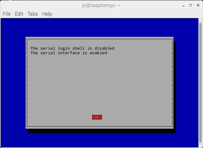
Then, reboot the Raspberry Pi.
Serial Port for UART Communication
By default, mini UART is mapped to UART pins (TX and RX) while PL011 is connected to on-board Bluetooth module on Raspberry Pi 3.
In previous version of Raspberry Pi models, PL011 is used for Linux Console output (mapped to UART pins) and there is no on-board Bluetooth module.
After making above configuration, UART can be used at UART pins (GPIO14 and GPIO15).
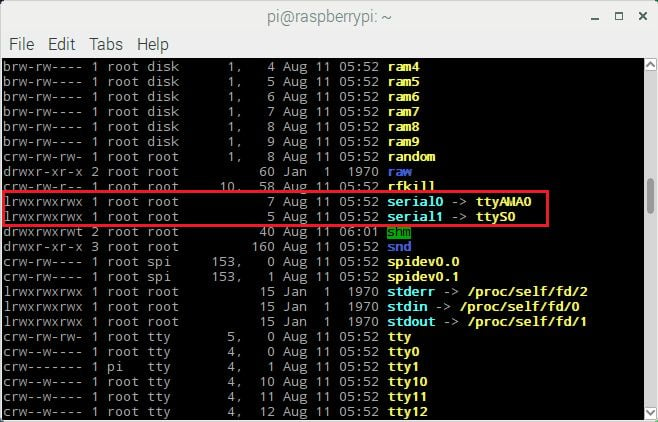
To access mini UART in Raspberry Pi 3, ttyS0 port is assigned. And to access PL011 in Raspberry Pi 3 ttyAMA0 port is assigned. But in other models of Raspberry Pi, there is only ttyAMA0 port is accessible.
Hardware UART port i.e. GPIO14(TXD) and GPIO15 (RXD) is also known as serial0 while other UART port which is connected to Bluetooth module is known as serial1.These names are created as serial aliases for Raspberry Pi version portability.
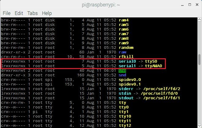
We can check which UART i.e. mini UART (ttyS0) or PL011 UART (ttyAMA0) is mapped to UART pins (GPIO14 and GPIO15). To check UART mapping, enter following commands.
ls -l /dev
The UART mapping for /dev/ttyS0 and /dev/ttyAMA0 is shown below,
Test serial communication in between Raspberry Pi and PC
To test that our Serial communication is working or not make the connections shown in below figure.
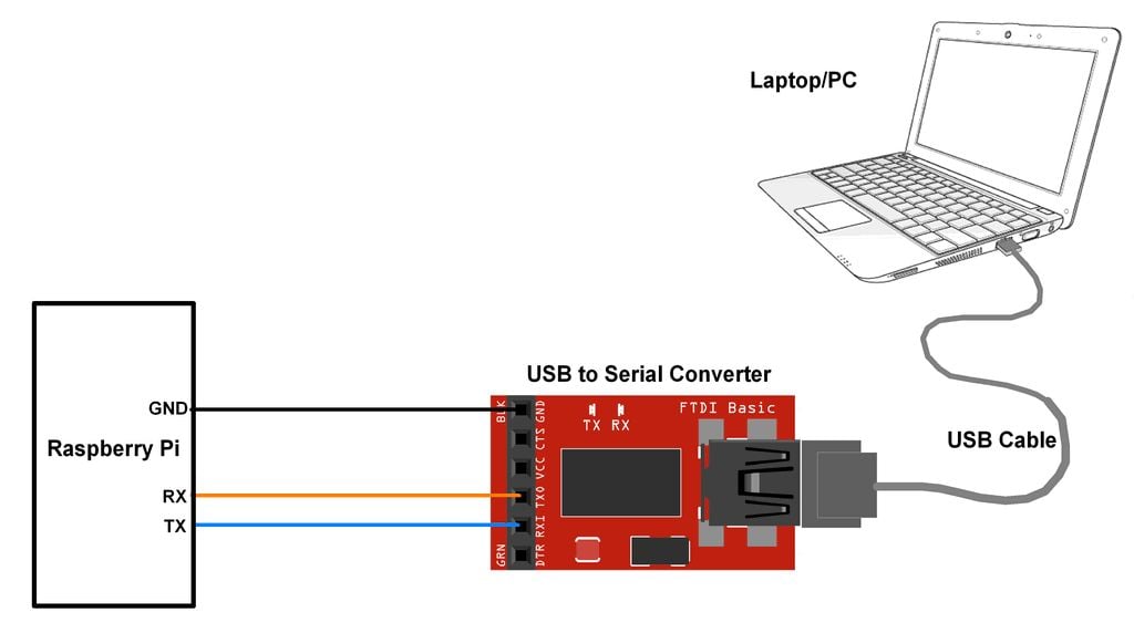
Open Terminal on Laptop/PC to receive the data which will be transmitted from the Raspberry Pi.
Now, enter the following command to transmit data from Raspberry Pi terminal.
echo “Hello” > /dev/ttyS0 This command will output “Hello” string on UART port i.e. Tx pin and will display it on terminal application of PC/Laptop.
By default, mini UART is mapped to the GPIO14 (TX) and GPIO15(RX). While PL011 i.e. ttyAMA0 is connected to the on-board Bluetooth module.
Example
Let’s establish serial communication between Raspberry Pi 3 and Laptop/PC using UART. We can perform UART based serial communication using Python and C.
Here, we will generate an echo on PC.
UART Communication on Raspberry Pi Using Python
'''
UART communication on Raspberry Pi using Pyhton
http://www.electronicwings.com
'''
import serial
from time import sleep

ser = serial.Serial ("/dev/ttyS0", 9600)    #Open port with baud rate
while True:
    received_data = ser.read()              #read serial port
    sleep(0.03)
    data_left = ser.inWaiting()             #check for remaining byte
    received_data += ser.read(data_left)
    print (received_data)                   #print received data
    ser.write(received_data)                #transmit data serially
Functions Used:
serial.Serial(port,baudrate)
It is a class for Serial which is used for opening port. Create instance for this class (here it is named as ser, we can use any name).
E.g.
ser = serial.Serial(/dev/ttyS0, 9600)Parameter:
Port – port name i.e. ttyUSB0, ttyS0, etc or None
Baudrate – Baud rate such as 9600, 38400, etc.
Above function has more parameter but that is not used here. So, for more parameter detail, you can refer Python API for PySerial.
read(Size)
This function is used to read the data on serial port.
Parameter:
Size – Number of Bytes to read. Default size is 1.
Return:
Bytes read from the port.
write(Data)
This function is used to transmit/send data on Serial Port.
Parameter:
Data – Data to send
Return:
Number of bytes written/sent
For more Serial APIs and their detail, you can refer Python API for PySerial.
UART Communication on Raspberry Pi using C
Let’s implement UART serial communication between Raspberry Pi 3 and Laptop/PC using program written in C language. Here, we are using WiringPi library to establish UART communication on Raspberry Pi.
/*
	UART communication on Raspberry Pi using C (WiringPi Library)
	http://www.electronicwings.com
*/

#include <stdio.h>
#include <string.h>
#include <errno.h>

#include <wiringPi.h>
#include <wiringSerial.h>

int main ()
{
  int serial_port ;
  char dat;
  if ((serial_port = serialOpen ("/dev/ttyS0", 9600)) < 0)	/* open serial port */
  {
    fprintf (stderr, "Unable to open serial device: %s\n", strerror (errno)) ;
    return 1 ;
  }

  if (wiringPiSetup () == -1)					/* initializes wiringPi setup */
  {
    fprintf (stdout, "Unable to start wiringPi: %s\n", strerror (errno)) ;
    return 1 ;
  }

  while(1){

	if(serialDataAvail (serial_port) )
	{
		dat = serialGetchar (serial_port);		/* receive character serially*/
		printf ("%c", dat) ;
		fflush (stdout) ;
		serialPutchar(serial_port, dat);		/* transmit character serially on port */
		  }
	}

}
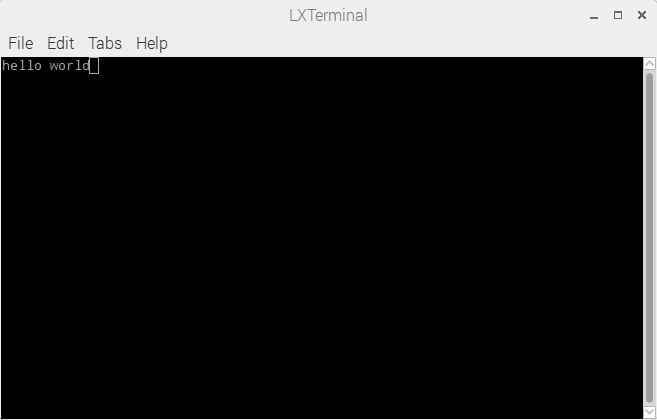
Output at Raspberry Pi Terminal
Output at Laptop/PC Terminal
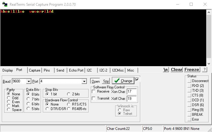
At PC/Laptop end, we use Realterm Software here.
Serial Aliases
Here, we have used ttyS0 port on which UART (GPIO14 and GPIO15) is mapped in Raspberry Pi 3. But in other models of Raspberry Pi it is mapped to ttyAMA0 as there is no on-board Bluetooth module.
So, the program written for Raspberry Pi 3 will give error on older models of Raspberry Pi as port name is different. To provide portability in port name, serial aliases are created in Raspbian named as serial0 and serial1. serial0 referred to UART port mapped to default port (ttyS0 or ttyAMA0). So, we can replace ttyS0 or ttyAMA0 with serial0.
When we use serial0 as UART port instead of ttyS0 or ttyAMA0 then the program written for Raspberry Pi 3 will also run on older models of Raspberry Pi.
Swapping Serial Ports on Raspberry Pi 3
For better performance, serial communication on GPIO14 and GPIO15 needs to use ttyAMA0 port which is connected to the Bluetooth module. To use this port, we should swap the UART ports i.e. map the ttyAMA0 to the GPIO14 and GPIO15 while ttyS0 (mini UART) to the Bluetooth module.
The swapping of serial ports can be done by using the mini UART (ttyS0) for Bluetooth module via a device overlay i.e. pi3-miniuart-bt. Or it can be done by completely disabling Bluetooth via device overlay i.e. pi3-disable-bt.
To swap the UART ports, open file config.txt as shown below,
sudo nano /boot/config.txtthen add below line to the end of the file as shown below,
dtoverlay = pi3-miniuart-btor
dtoverlay = pi3-disable-btAfter adding above line, save the changes to the file and reboot the system.
We can check the new mapping of serial ports by,
ls -l /devThe mapping of UART port is shown below,
Components Used |
||
|---|---|---|
| Raspberry Pi 4B Raspberry Pi 4BRaspberry Pi 4B |
X 1 | |
| CP2103 USB TO UART BRIDGE CP2103 is single chip USB to UART Bridge. It supports USB 2.0 protocol. |
X 1 | |
| Raspberry Pi Zero Raspberry Pi Zero |
X 1 | |