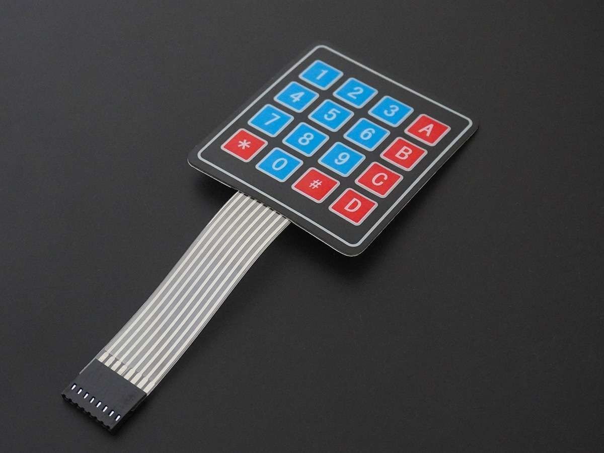
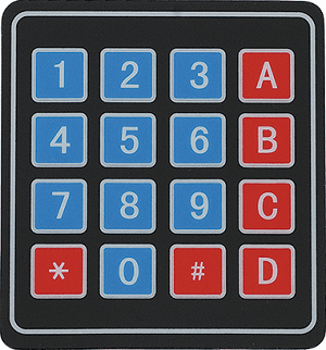
Overview of 4x4 Matrix Keypad
Keypad is used as an input device to read the key pressed by the user and to process it.
4x4 keypad consists of 4 rows and 4 columns. Switches are placed between the rows and columns.
A key press establishes a connection between the corresponding row and column, between which the switch is placed.
For more information about keypad and how to use it, refer the topic 4x4 Keypad in the sensors and modules section.
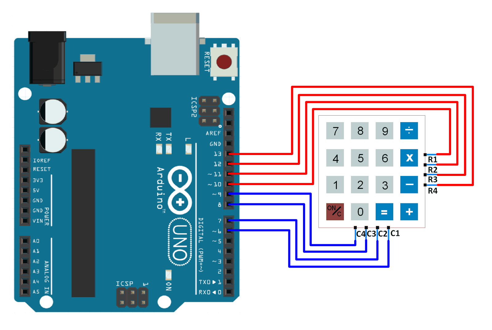
Connection Diagram of 4x4 Keypad with Arduino UNO
Read the 4x4 Keypad using Arduino Uno
Reading the key pressed on the 4x4 keypad and displaying it on the serial terminal of Arduino.
Here, we will be using the Keypad library by Mark Stanley and Alexander Brevig.
Download this library from here.
Extract the library and add it to the libraries folder path of Arduino IDE.
For information about how to add a custom library to the Arduino IDE and use examples from it, refer Adding Library To Arduino IDE in the Basics section.
Once the library has been added to the Arduino IDE, open the IDE and open the example sketch for CustomKeypad from the library added.
Word of Caution:
In the example sketch Custom Keypad included in the Keypad library, digital pins 0 and 1 are used for connecting rows. This will result in those rows not working for some people.
The Arduino UNO board has digital pins 0 and 1 connected to the Tx and Rx pins which are used for serial communication. Since the sketch uses serial communication to display the key pressed on serial terminal, this will cause erroneous behavior.
To avoid this, use pins other than pins 0 and 1. You can refer the sketch given below to get an idea about how to do this.
Note:
byte rowPins[ROWS] = {R1, R2, R3, R4}; /* connect to the row pinouts of the keypad */
byte colPins[COLS] = {C1, C2, C3, C4}; /* connect to the column pinouts of the keypad */
If you do not connect the pins according to this function, the key press identification will not give results according to the keypad you have defined.
4x4 Keypad Code for Arduino Uno
/* @file CustomKeypad.pde
|| @version 1.0
|| @author Alexander Brevig
|| @contact [email protected]
||
|| @description
|| | Demonstrates changing the keypad size and key values.
|| #
*/
#include <Keypad.h>

const byte ROWS = 4; /* four rows */
const byte COLS = 4; /* four columns */
/* define the symbols on the buttons of the keypads */
char hexaKeys[ROWS][COLS] = {
  {'0','1','2','3'},
  {'4','5','6','7'},
  {'8','9','A','B'},
  {'C','D','E','F'}
};
byte rowPins[ROWS] = {10, 11, 12, 13}; /* connect to the row pinouts of the keypad */
byte colPins[COLS] = {6, 7, 8, 9}; /* connect to the column pinouts of the keypad */

/* initialize an instance of class NewKeypad */
Keypad customKeypad = Keypad( makeKeymap(hexaKeys), rowPins, colPins, ROWS, COLS);

void setup(){
Serial.begin(9600);
}

void loop(){
  char customKey = customKeypad.getKey();

  if (customKey){
Serial.println(customKey);
  }
}
Video of 4x4 Keypad With Arduino Uno
Functions Used
1. makeKeymap(keys)- This function is used to initialize the internal keymap to be equal to the user defined key map (in function syntax given above, keys).
2. Keypad customKeypad = Keypad( makeKeymap(keys), rowPins, colPins, rows, cols)- This defines an object customKeypad of the class Keypad and initializes it.
- rowPins and colPins are the pins on Arduino to which the rows and columns of the keypad are connected to.
- rows and cols are the number of rows and columns the keypad has.
3. customKeypad.getKey()- This function is used to identify which key is pressed on the keypad.
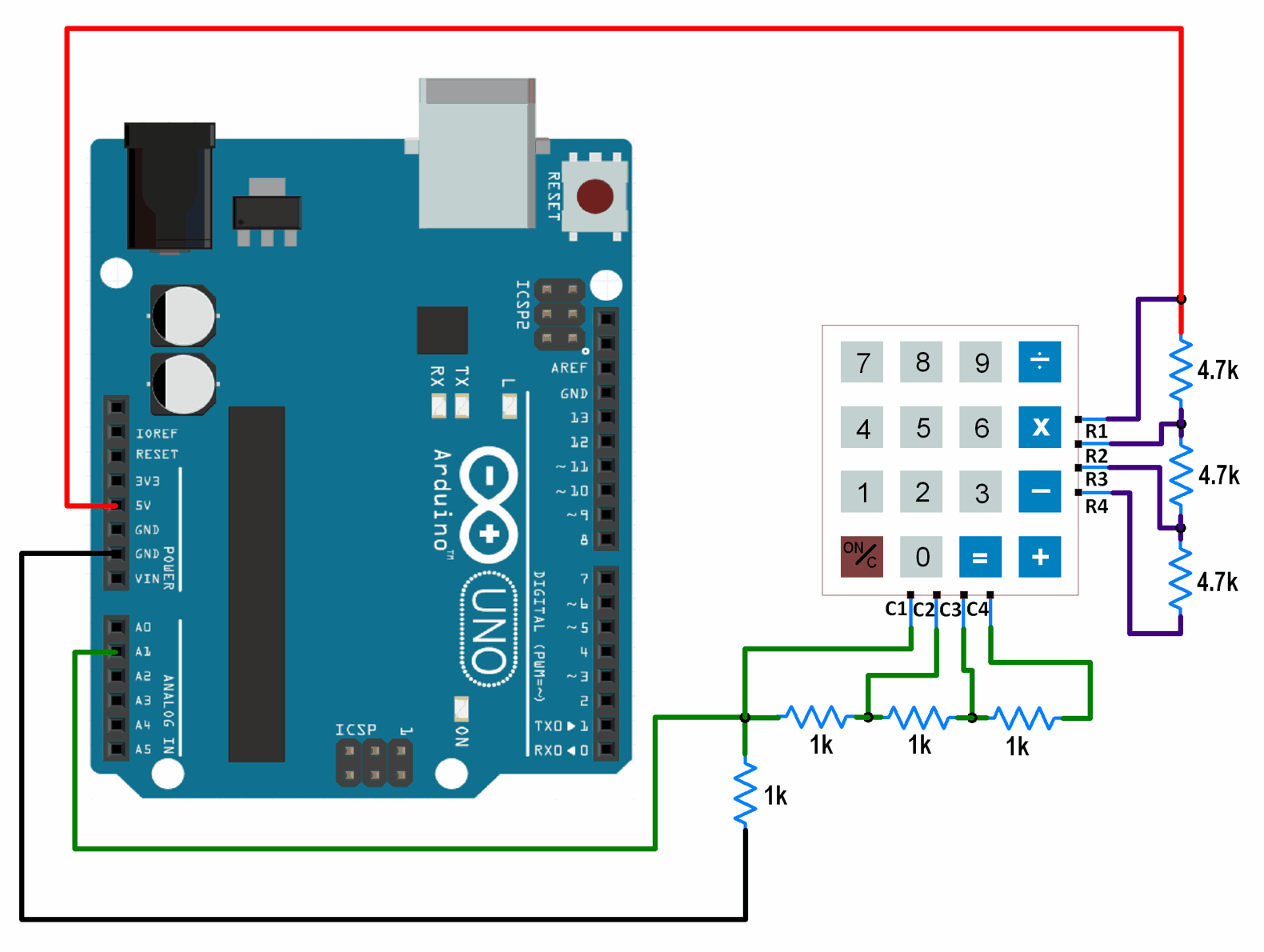
1-Wire interfacing of Keypad With Arduino
The above shown interfacing consumes 8 GPIO pins of the Arduino board. By using the 1-wire interfacing method for a keypad, we can achieve the same result as above using just 1 GPIO pin.
This method makes use of simple voltage divider concept to generate different voltages for each key pressed.
Let’s see how to interface keypad to Arduino using a single GPIO pin.
Connection Diagram of 1-Wire Keypad Interface With Arduino
One Wire Keypad Code for Arduino Uno
void setup() {
  Serial.begin(9600);	/* Define baud rate for serial communication */
}

void loop() {
  int adc_val;
  adc_val = analogRead(A1);	/* Read input from keypad */
  if (adc_val>850)
  {
    Serial.print("Key Pressed : ");
    Serial.println("0");
    delay(100);
  }
  else if ( adc_val>450  && adc_val<510)
  {
    Serial.print("Key Pressed : ");
    Serial.println("1");
    delay(100);
  }
  else if ( adc_val>300  && adc_val<350)
  {
    Serial.print("Key Pressed : ");
    Serial.println("2");
    delay(100);
  }
  else if ( adc_val>230  && adc_val<270)
  {
    Serial.print("Key Pressed : ");
    Serial.println("3");
    delay(100);
  }
  else if ( adc_val>160  && adc_val<180)
  {
    Serial.print("Key Pressed : ");
    Serial.println("4");
    delay(100);
  }
  else if ( adc_val>145  && adc_val<155)
  {
    Serial.print("Key Pressed : ");
    Serial.println("5");
    delay(100);
  }
  else if ( adc_val>125  && adc_val<135)
  {
    Serial.print("Key Pressed : ");
    Serial.println("6");
    delay(100);
  }
  else if ( adc_val>105  && adc_val<120)
  {
    Serial.print("Key Pressed : ");
    Serial.println("7");
    delay(100);
  }
  else if ( adc_val>92  && adc_val<99)
  {
    Serial.print("Key Pressed : ");
    Serial.println("8");
    delay(100);
  }
  else if ( adc_val>82  && adc_val<90)
  {
    Serial.print("Key Pressed : ");
    Serial.println("9");
    delay(100);
  }
  else if ( adc_val>77  && adc_val<81)
  {
    Serial.print("Key Pressed : ");
    Serial.println("A");
    delay(100);
  }
  else if ( adc_val>72  && adc_val<76)
  {
    Serial.print("Key Pressed : ");
    Serial.println("B");
    delay(100);
  }
  else if ( adc_val>63  && adc_val<68)
  {
    Serial.print("Key Pressed : ");
    Serial.println("C");
    delay(100);
  }
  else if ( adc_val>60  && adc_val<62)
  {
    Serial.print("Key Pressed : ");
    Serial.println("D");
    delay(100);
  }
  else if ( adc_val>57  && adc_val<59)
  {
    Serial.print("Key Pressed : ");
    Serial.println("E");
    delay(100);
  }
  else if( adc_val>52  && adc_val<56)
  {
    Serial.print("Key Pressed : ");
    Serial.println("F");
    delay(100);
  }
  else
  {

  }
  delay(100);
}
Word of Caution : The ADC values used for deciding the key presses have been found out practically. You might need to find out the ADC values practically. These values have been found out for the resistor combination shown in the interfacing diagram. If you use other resistor values, the above code will give faulty output. If you decide to use other resistor values, you will have to find out the ADC values for each key press and make changes accordingly in the code.
Components Used |
||
|---|---|---|
| Arduino Nano Arduino Nano |
X 1 | |
| Arduino UNO Arduino UNO |
X 1 | |
| 4x4 Keypad Module Keypad is an input device which is generally used in applications such as calculator, ATM machines, computer etc. |
X 1 | |