The Arduino UNO board is one of the most popular Arduino boards and is a good starting point if it is your first Arduino.
The Arduino UNO has undergone a few revisions over the period of time, with the latest board being the Arduino UNO R3.
You will not find many significant changes between the revisions. The most significant change is that the R3 uses an ATmega16U2 for USB-to-serial conversion. The ATmega16U2 is programmed for USB-to-serial conversion. (up to R2, ATmega8U2 was used for USB-to-serial conversion, whereas the boards prior to UNO used FTDI USB-to-serial driver chips).
Arduino Uno Pin Diagram
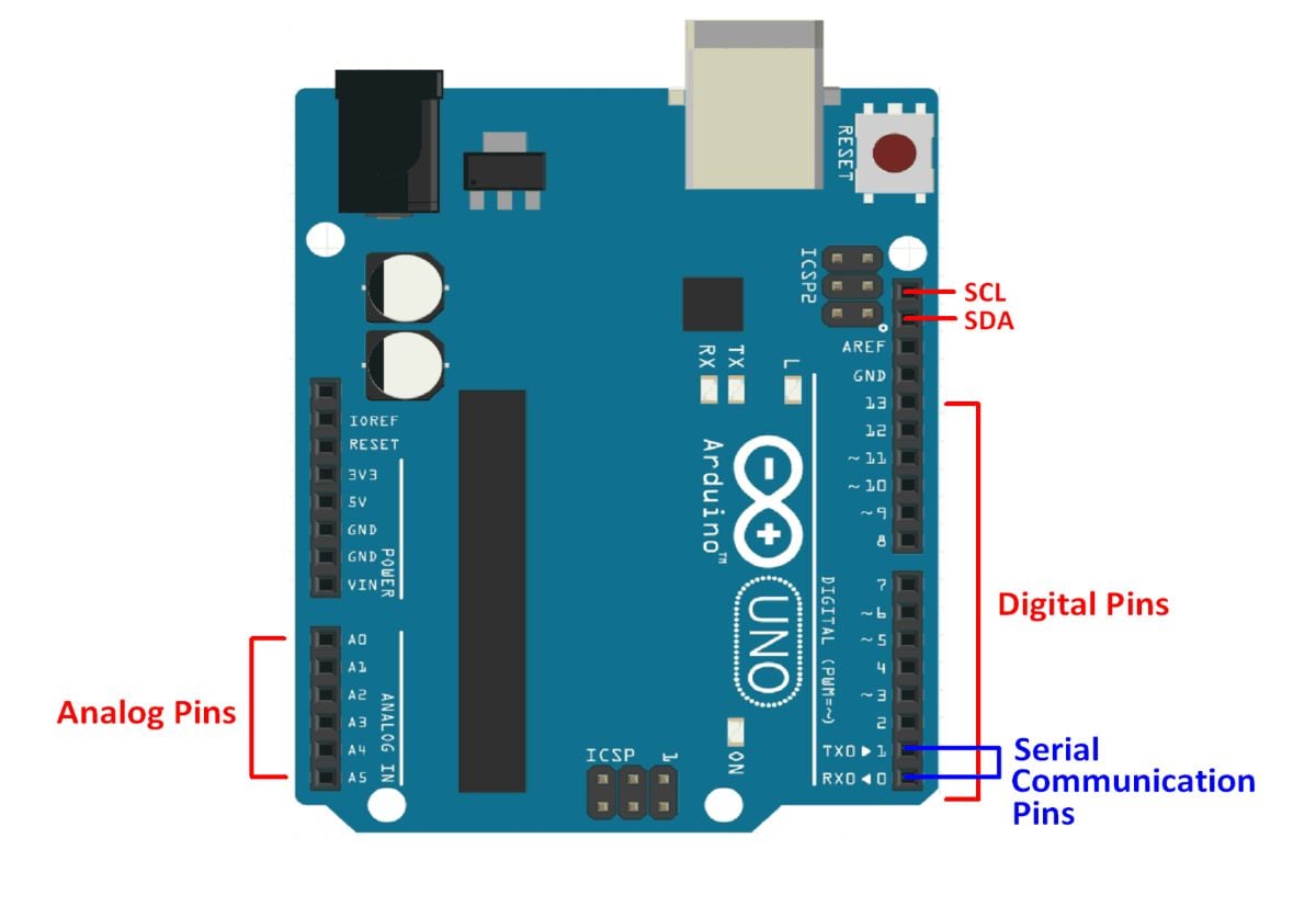
The above image shows the Arduino UNO R3 board.
Arduino UNO R3 uses ATmega328P microcontroller as the main control and processing unit of the board. The Atmega328P has 32kB In-System Programmable Flash Memory, 1kB EEPROM, and 2kB internal SRAM.
The UNO board provides access to 14 Digital I/O pins (0-13 in the above image). Of these 14 digital I/O pins, 6 pins can be used as PWM pins(pins 3,5,6,9,10 and 11). The PWM pins are indicated by ~ before the pin number on the Arduino UNO boards (E.g. ~3).
Digital pins 0 and 1 are the serial communication pins RX and TX respectively.
6 pins are available for use as Analog input pins (A0-A5). The analog pins can be used as digital I/O pins as well if there is no analog input to be measured.
Note : The numbers given to the pins on the board are not the pin numbers of the ATmega328P microcontroller. These are the pin numbers used while accessing the functions from the Arduino libraries.
Table given below shows which pin on the UNO board is connected to which pin on the ATmega328P microcontroller.
Table : Atmega328P Pin Mapping with Arduino Uno
| Pin on Arduino UNO | Pin on ATmega328P |
| 0 | 2 |
| 1 | 3 |
| 2 | 4 |
| 3 | 5 |
| 4 | 6 |
| 5 | 11 |
| 6 | 12 |
| 7 | 13 |
| 8 | 14 |
| 9 | 15 |
| 10 | 16 |
| 11 | 17 |
| 12 | 18 |
| 13 | 19 |
| A0 | 23 |
| A1 | 24 |
| A2 | 25 |
| A3 | 26 |
| A4 | 27 |
| A5 | 28 |
| GND | 8,22 |
| 5V | 7 |
| AREF | 21 |
| RESET | 1 |
The Arduino UNO board can be powered through
- A USB cable
- An external AC-DC adapter (output voltage of the adapter must be fixed and within the range of 7V to 12V). Adapter needs to be plugged into the power jack.
- A battery (Fixed voltage, the voltage must be in the range of 7V to 12V). Battery terminals must be connected between VIN and GND pins on the board.
Note : While uploading the sketch using Arduino IDE, make sure that there are no connections from other devices to pins 0 and 1 of UNO board. These are the Rx and Tx pins of ATmega328P, and are used while uploading the sketch.
Components Used |
||
|---|---|---|
| Arduino Nano Arduino Nano |
X 1 | |
| Arduino UNO Arduino UNO |
X 1 | |