Overview of SSD1306 OLED Display
.jpg)
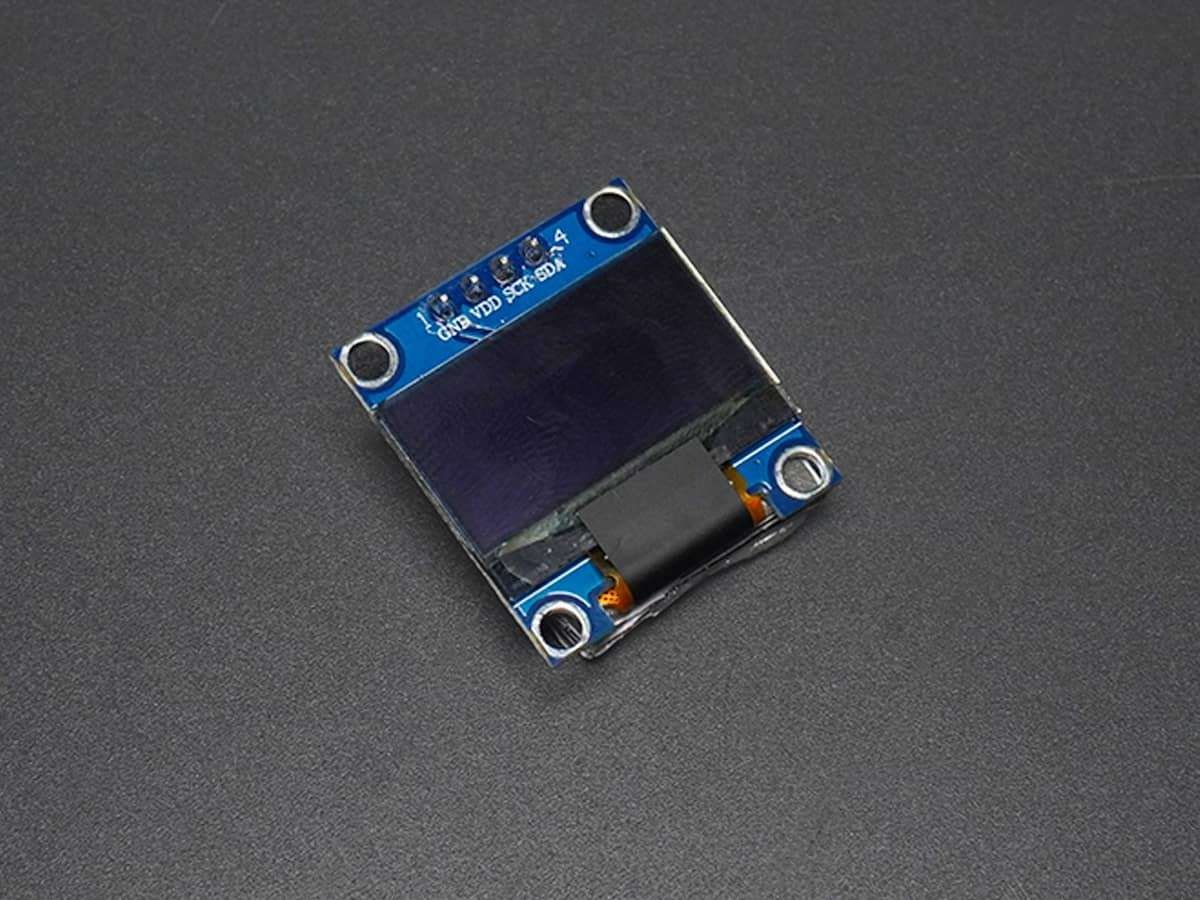
The OLED module shown in the above image is a very popular module available in the market.
There are many variants of this module available in the market, having different resolutions, communication protocol, or pixel colors.
They do not require backlight since the display creates its own light. Hence, they consume less power. Both I2C and SPI based OLED modules are available in the market.
For more information about OLED Display Structure and its commands refer SD1306 OLED Display
A NodeMCU can communicate with this module using the I2C communication protocol. To know more about I2C functions in NodeMCU refer to NodeMCU I2C with ESPlorer IDE or NodeMCU I2C with Arduino IDE
SSD1306 OLED Pinout Description
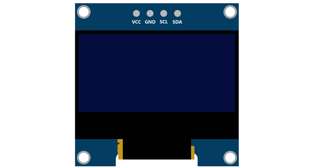
SSD1306 OLED Pin Description
VCC: This is the power pin for the module. A supply of 3.3V or 5V can be provided to this pin to power the display.
GND: This is the ground pin for the module.
SCL and SDA: These are the serial clock and serial data pins for I2C Interface.
Connection Diagram of SSD1306 128x64 OLED with NodeMCU
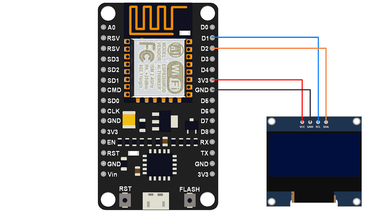
SSD1306 OLED Display using NodeMCU
Displaying timer based on delay function on the 128x64 OLED Display module.
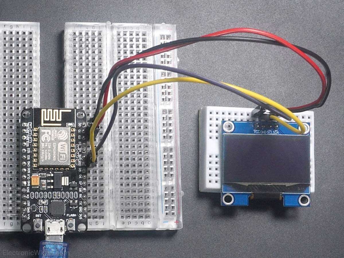
First, do the connections as shown in the above interfacing diagram.
We can write codes for NodeMCU DevKit in either Lua Script or C/C++ language. We are using ESPlorer IDE for writing code in Lua scripts and Arduino IDE for writing code in C/C++. To know more refer to Getting started with NodeMCU using ESPlorer IDE (which uses Lua scripting for NodeMCU) and Getting started with NodeMCU using Arduino IDE (which uses C/C++ language based Arduino sketches for NodeMCU).
Let’s first write Lua Script for NodeMCU using ESPlorer IDE
Lua Script for NodeMCU
sda = 2 -- SDA Pin
scl = 1 -- SCL Pin

s=0
m=0
h=0

function init_OLED(sda,scl) --Set up the u8glib lib
    sla = 0x3C
    i2c.setup(0, sda, scl, i2c.SLOW)
    disp = u8g.ssd1306_128x64_i2c(sla)
    disp:setFont(u8g.font_6x10)
    disp:setFontRefHeightExtendedText()
    disp:setDefaultForegroundColor()
    disp:setFontPosTop()
    --disp:setRot180()           -- Rotate Display if needed
end

function write_OLED() -- Write Display
    disp:firstPage()
    repeat
     disp:drawStr(50, 10, "Timer")
     disp:drawStr(40, 30,  string.format("%02d:%02d:%02d",h,m,s))
     disp:drawStr(20, 50, "ElectronicWings")
    until disp:nextPage() == false
end

-- Main Program
init_OLED(sda,scl)

tmr.alarm(0, 1000, 1, function() -- Every second increment clock and display
    s = s+1
    if s==60 then
     s=0
     m=m + 1
    end
    if m==60 then
     m=0
     h=h + 1
    end
    if h==13 then
     h=1
    end
    write_OLED()
end)
Now let’s write an Arduino sketch for NodeMCU using Arduino IDE.
Here, we are using the Adafruit library for SSD1306. This library is available on GitHub.
Download Adafruit ssd1306 library from here.
Note: This library is for monochrome displays only.
We will need the Adafruit GFX library as well for the patterns and text that we will be displaying on the display.
Download Adafruit GFX library from here.
Extract these libraries and add them to the libraries folder path of Arduino IDE.
For information about how to add a custom library to the Arduino IDE and use examples from it, refer to Adding Library to Arduino IDE in the Basics section.
The Adafruit library for SSD1306 comes with 4 examples sketch. You can directly upload one of the sketches (depending on your device and communication protocol supported) to your device.
Here we have written an example sketch of our own based on the functions defined in the two libraries.
Note: If you use the example sketches, ensure that you use the appropriate I2C device address. In the Adafruit library, the device address used is either 0x3C or 0x3D. Use one of these addresses. You will have to find out which one is your device’s address. This address is not the 8-bit device address; it is the address that is formed by the 7-bits without considering the read or writes a bit. Try one of these addresses, if it does not work, use the other.
SSD1306 OLED Code for NodeMCU using Arduino IDE
#include <SPI.h>
#include <Wire.h>
#include <Adafruit_GFX.h>
#include <Adafruit_SSD1306.h>

#define OLED_RESET D5
/* Object named display, of the class Adafruit_SSD1306 */
Adafruit_SSD1306 display(OLED_RESET);

#if (SSD1306_LCDHEIGHT != 64)
#error("Height incorrect, please fix Adafruit_SSD1306.h!");
#endif

uint8_t s = 0, m = 0, h = 0;

void setup()   {
  display.begin(SSD1306_SWITCHCAPVCC, 0x3C); /* Initialize display with address 0x3C */
  display.clearDisplay();  /* Clear display */
  display.setTextSize(1);	/* Select font size of text. Increases with size of argument. */
  display.setTextColor(WHITE);	/* Color of text*/
}

void loop() {
  updateWatch();/* Every second increment clock and display */
  delay(1000);
}

void updateWatch() {
  s = s + 1;
  if (s == 60) {
    s = 0;
    m = m + 1;
  }
  if (m == 60) {
    m = 0;
    h = h + 1;
  }
  if (h == 13)
    h = 1;

  writeOLED();
}

void writeOLED(){
  char time[30];
  display.clearDisplay();  /* Clear display */
  sprintf(time, "%02d:%02d:%02d", h, m, s);
  drawStr(50, 10, "Timer");
  drawStr(40, 30, time);
  drawStr(20, 50, "ElectronicWings");
  display.display();
}

void drawStr(uint8_t x, uint8_t y, char* str){
  display.setCursor(x, y);  /* Set x,y coordinates */
  display.println(str);
}
Note: If we get the below error while compiling the program in Arduino IDE
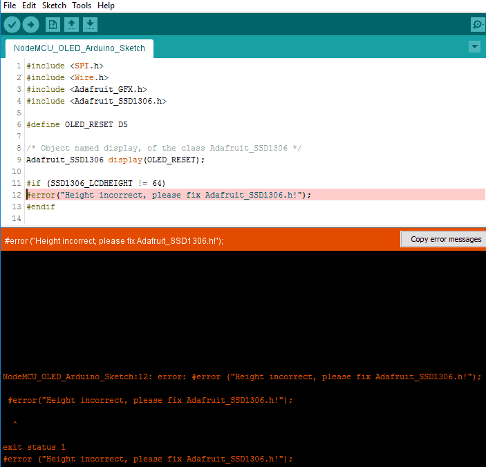
Then it will tell us that we are selecting incorrect height for display.
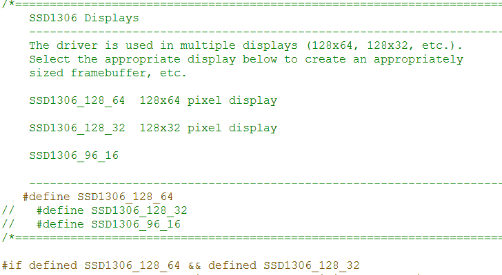
128x64 display has 64 height,
128x32 display has 32 height,
Hence, we need to select an appropriate display.
We can select the display frame size in the Adafruit_SSD1306.h file which is in the Adafruit ssd1306 library folder (which we have previously copied in the Arduino library folder).
Just uncomment the line of proper display we are using and comment out others. Here we are using a 128x64 frame size display hence we have uncommented it as shown in the below image.
Video of SSD1306 OLED Module With NodeMCU
Components Used |
||
|---|---|---|
| SSD1306 OLED display OLED (Organic Graphic Display) display modules are compact and have high contrast pixels which make this display easily readable. They do not require backlight since the display creates its own light. Hence they consume less power. It is widely used in Smartphones, Digital display. |
X 1 | |
| NodeMCU NodeMCUNodeMCU |
X 1 | |
| ESP12F ESP12E |
X 1 | |