Introduction
Analog to Digital Converter(ADC) is used to convert the analog signals into digital form. ESP8266 has an inbuilt 10-bit ADC with only one ADC channel i.e. it has only one ADC input pin to read the analog voltage from external device/sensor.
ADC pin on NodeMCU DevKit
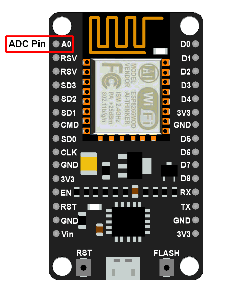
ADC pin on NodeMCU DevKit
The ADC channel on ESP8266 is multiplexed with the battery voltage. Hence, we can set it to measure either onboard supply voltage or external analog voltage. The input voltage range for the ADC pin is 0–1.0V while reading external analog voltage.
The setting for ADC mode i.e. whether system voltage or external voltage is being measured is available in the 107th byte of “esp_init_data_default.bin” (0-127 byte) of the firmware.
The 107th byte of esp_init_data_default.bin (0 - 127 byte) is “vdd33_const“. It must be set to 0xFF i.e. 255 to read system voltage i.e. voltage on VDD pin of ESP8266.
And to read the external voltage on the ADC pin it must be set to power supply voltage on the VDD pin of ESP8266. The working power voltage range of ESP8266 is between 1.8V and 3.6V, and the unit of “vdd33_const“ is 0.1V, therefore, the value range of “vdd33_const“ is in between 18 to 36.
For more information on the “vdd33_const“ refer ADC section of the ESP8266 datasheet attached at the end of this document.
Note that the NodeMCU Dev Kit shown in the below figure has an onboard register divider network which provides 1.0V from 3.3V to the ADC pin of ESP8266. Hence, we can use a 0–3.3V range for ADC input voltage for NodeMCU Dev Kit. Since 10-bit resolution, it will give 0-1023 value range for ADC input voltage 0-3.3V on Dev Kit.
adc.force_init_mode() (explained below) the function is used to select the mode i.e. ADC to read system voltage or ADC to read external voltage.
It is mandatory to restart the system (e.g. using power cycle, reset button, node.restart()) if the mode is changed.
NodeMCU ADC Functions
Let’s see ADC functions that are used for accessing ADC on NodeMCU Dev Kit.
adc.force_init_mode()
Checks and if necessary reconfigures the ADC mode setting in the ESP init data block.
Syntax:
adc.force_init_mode(mode_value)
Parameters:
mode_value is either adc.INIT_ADC for external voltage or adc.INIT_VDD33 for onboard system voltage.
Returns:
It returns true if the function had to change the mode, else false if the mode was already configured. On a true return, the ESP needs to be restarted for the change to take effect.
Example:
if adc.force_init_mode(adc.INIT_VDD33)
then
  node.restart()
  return
end
adc.read()
This function reads the analog voltage on the ADC pin.
Syntax:
adc.read(channel)
Parameters:
ADC channel is only one and it is always 0 on the ESP8266
Returns: Sampled digital value.
Note that If the ESP8266 has been configured to use the ADC for reading the system voltage, this function will always return 65535. This is a hardware and/or SDK limitation.
Example:
ADC value = adc.read(0)
adc.readvdd33()
This function reads the system voltage.
Syntax:
adc.readvdd33()
Parameters: none
Returns: It returns system voltage in millivolts (number)
If the ESP8266 has been configured to use the ADC for sampling the external voltage on pin, this function will always return 65535. This is a hardware and/or SDK limitation.
Example:
print("System voltage (mV):", adc.readvdd33(0))
Example
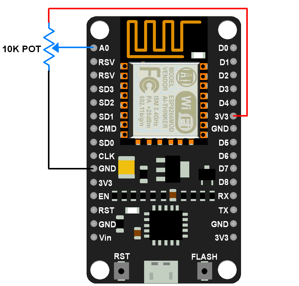
Let’s write a Lua script to read the analog voltage on the ADC pin of NodeMCU. Here we use a potentiometer to provide variable voltage from 0-3.3V on the ADC pin of Dev Kit. Connect pot as shown in the below diagram.
Now write Lua script for reading the ADC channel and print digital value on serial monitor of ESPlorer.
Lua Script for reading external voltage
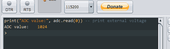
print("ADC value:", adc.read(0)) -- print external voltageOutput window
The below figure shows output on the serial monitor of ESPlorer IDE
Lua Script for reading System voltage
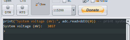
print("System voltage (mV):", adc.readvdd33(0)) -- print system voltageOutput window
The below figure shows output on the serial monitor of ESPlorer IDE
The system voltage (power supply voltage) value is a little bit diverted from its actual value. this issue about system voltage reading is given at #721 on the ESP8266 Github page.
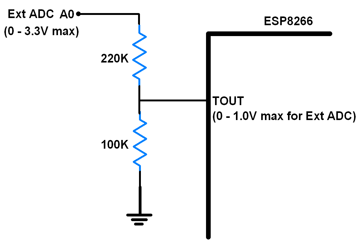
According to the datasheet of ESP8266, the TOUT (ADC pin of ESP8266) pin must be dangled (floating) while measuring the power supply voltage through ADC. But on NodeMCU Dev Kit/Modules it is connected to the voltage divider network of resistors (100Kohm & 220Kohm) for the sake of external voltage range (0-3.3V) support as shown in below figure.
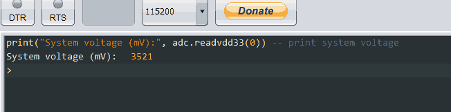
Now if we remove resister divider n/w and ADC pin (TOUT) left floating then we get results as shown in below output window image of the system voltage reading. i.e. 3521 mV.
Components Used |
||
|---|---|---|
| NodeMCU NodeMCUNodeMCU |
X 1 | |
| ESP12F ESP12E |
X 1 | |