Description
- Mostly we have used the PIR sensor for motion detection. However, it detects the movement of only living things.
- Basically, living body temperature is higher than 0 °C and it emits heat in the form of infrared radiation.
- However, Microwave sensor like RCWL -0516 detects the movement of any object (living and non-living). For hotter environments, it becomes more reliable than a PIR sensor.
- Also the RCWL-0516 has a 360-degree coverage with a claimed range of 3-7 meters, the PIR sensor only has a directional coverage of 110' with a similar 3-7 meter range
How RCWL-0516 Microwave Radar Sensor Works
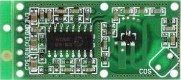
- The RCWL-0516 is a microwave motion sensor module used where motion detection is required.
- The module has its own transmitter and receiver the transmitter transmits the continuous microwave signals, while the receiver receives the reflected signals after they bounce off objects within the sensor's range.
- This module operates on the principle of the Doppler effect. When an object moves within the sensing range, it causes a change in the frequency of the reflected microwave signals received by the receiver.
- This frequency shift is proportional to the velocity of the moving object.
- To detect objects of different sizes and movement speeds by using its sensitivity adjustments, we can adjust its range typically from a few meters to tens of meters.
- This module supports two sensing modes: presence detection and motion detection.
- The presence detection mode detects the presence of object within its range, regardless of whether it is moving or not.
- The motion detection mode detects the movement of objects within its range.
- When motion or the presence of an object is detected, the RCWL-0516 module outputs a high signal (logic level 1) on its output pin.
- This signal can be connected to a microcontroller to trigger actions, such as turning on lights, activating alarms, or controlling other components.
Specification of RCWL-0516 Radar Sensor
- Operating Voltage 4-28V (typically 5V)
- Detection Distance 5-9 meters
- Maximum Current Draw ~ 3mA
- Operating Frequency ~3.2GHz
- Transmission Power 30mW (max.)
- Output Timing ~ 2s
- Regulated Output 3.3V, 100mA
Pin Diagram of RCWL-0516 Radar Sensor
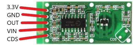
- VIN: is the power supply for the sensor. You can connect an input voltage anywhere between 4 to 28V to this pin, although 5V is commonly used.
- GND: is the ground pin.
- 3.3V: This is the regulated output pin of 3.3V/100mA
- OUT: This is the 3.3V TTL logic output. It goes HIGH for two seconds when motion is detected and goes LOW when idle (no motion detected).
- CDS: CDS is a cadmium sulfide pin where we can connect the LDR to allow the RCWL-0516 to operate only in the dark.
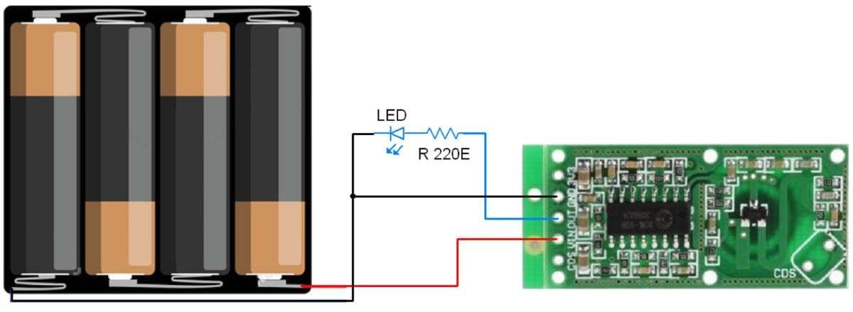
Let’s test Readar Sensor RCWL-0516
- Let’s test the radar sensor RCWL-0516 in a simple way.
- Connect four AA batteries to the VIN and GND pin of the sensor and a small red LED to the output pin through a 220Ω resistor to limit the current
- When the sensor detects the motion, the LED will be ON.
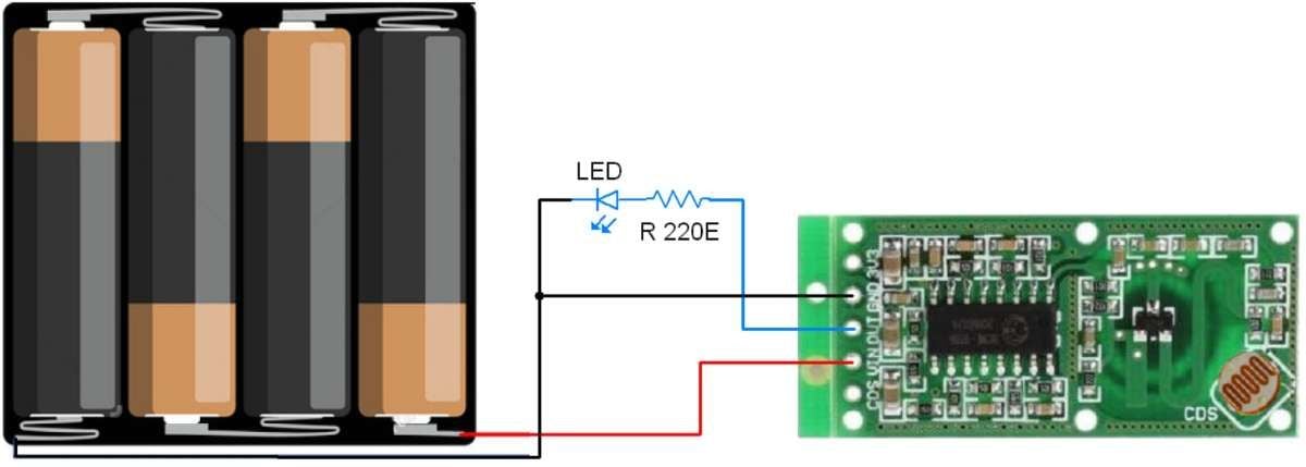
Let’s Test with LDR (Light Dependant Resistor)
- Connect the LDR to the RCWL-0516 sensor, There are two options to connect the LDR first is to connect to the two CDS pads on the top of the sensor, and the second is to use the CDS pin and ground pin on the bottom.
- When the light is falling on LDR we noticed there is no output from the sensor, and then placed it in a dark room it started normal operation.
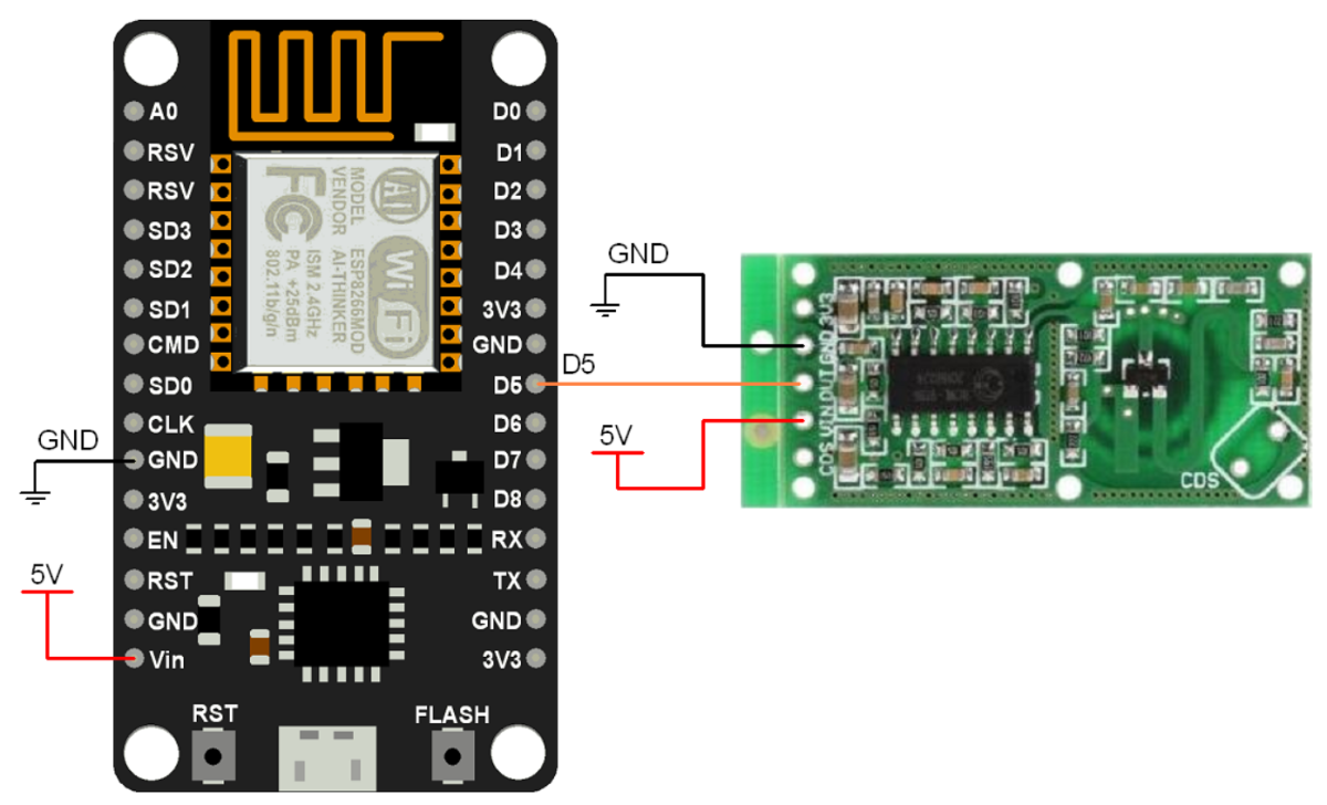
Interfacing Diagram of RCWL-0516 Radar Sensor with Nodemcu
RCWL-0516 Radar Sensor Code for Nodemcu using Arduino IDE
int sensorPin = D5;
int motionState = LOW;

void setup() {
  Serial.begin(9600);
  pinMode(sensorPin, INPUT);
}

void loop() {
  if (digitalRead(sensorPin) == HIGH) {
    if (motionState == LOW) {
     Serial.println("Motion detected!");
      motionState = HIGH;
    }
  }

  else {
    if (motionState == HIGH) {
     Serial.println("Motion ended!");
      motionState = LOW;
    }
  }
}
- Now upload the code.
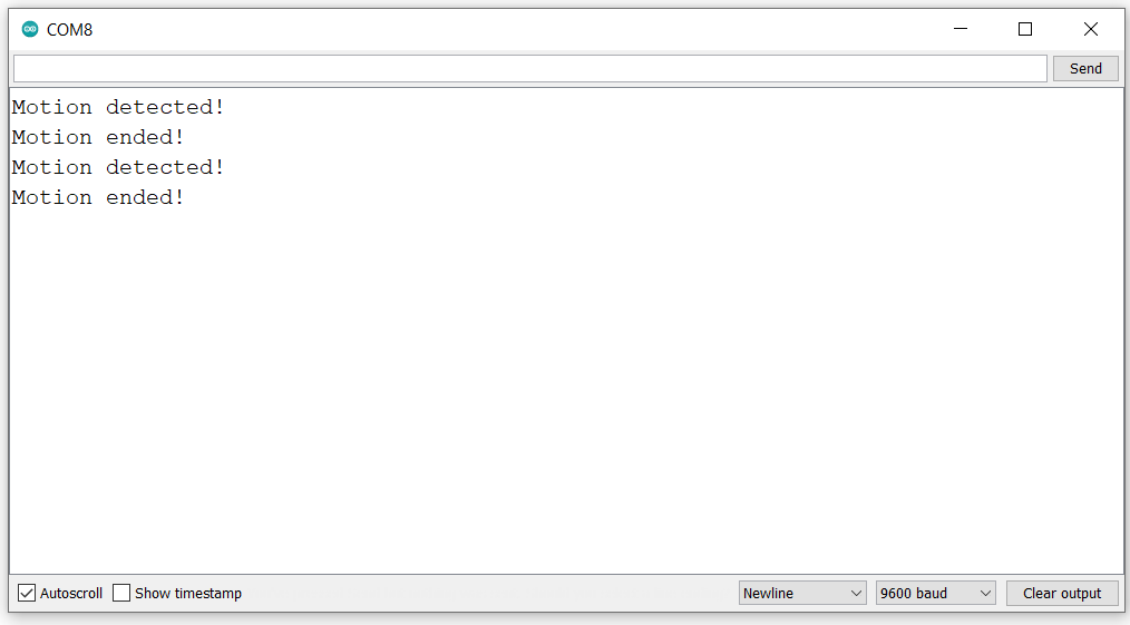
- After uploading the code open the serial monitor and set the baud rate to 9600 to see the output.
Output
Let’s Understand the code
Assign the pin number of nodemcu as an input pin from sensor
int sensorPin = D5;
int motionState = LOW;
Initialize and set the serial communication baudrate to 9600
Serial.begin(9600);Set the sensorPin as an INPUT
pinMode(sensorPin, INPUT);In the loop, read the sensorPin output and check the motion status. If motion is detected then print on serial monitor Motion is detected!
  if (digitalRead(sensorPin) == HIGH) {
    if (motionState == LOW) {
     Serial.println("Motion is detected!");
      motionState = HIGH;
    }
  }
Else print on the serial monitor motion end!
  else {
    if (motionState == HIGH) {
     Serial.println("Motion end!");
      motionState = LOW;
    }
  }
Components Used |
||
|---|---|---|
| NodeMCU NodeMCUNodeMCU |
X 1 | |
Downloads |
||
|---|---|---|
|
|
RCWL-0516_Radar_Sensor_Code_for_Nodemcu | Download |