Introduction
Analog to Digital Converter (ADC) is used to convert the analog signal into digital form. ESP8266 has an inbuilt 10-bit ADC with only one ADC channel i.e. it has only one ADC input pin to read the analog voltage from an external device.
ESP8266 ADC pin on NodeMCU Kit
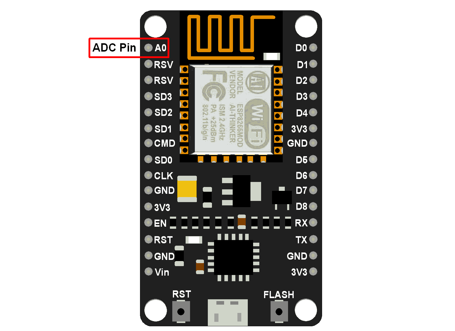
The ADC channel on ESP8266 is multiplexed with the battery voltage. Hence, we can set it to measure either onboard system voltage or external voltage. The input voltage range for the ADC pin is 0–1.0V while reading external voltage.
The setting for ADC mode i.e. whether system voltage or external voltage is being measured is available in the 107th byte of “esp_init_data_default.bin” (0-127 byte) of the firmware.
The 107th byte of esp_init_data_default.bin (0 - 127 byte) is “vdd33_const“. It must be set to 0xFF i.e. 255 to read system voltage i.e. voltage on VDD pin of ESP8266.
And to read the external voltage on the ADC pin it must be set to power supply voltage on the VDD pin of ESP8266. The working power voltage range of ESP8266 is between 1.8V and 3.6V, and the unit of “vdd33_const“is 0.1V, therefore, the value range of “vdd33_const” is 18 to 36.
For more information on “vdd33_const“, refer to the ADC section of the ESP8266 datasheet attached at the end of this document.
Note that the NodeMCU Dev Kit shown in the below figure has an onboard register divider network which provides 1.0V from 3.3V to the ADC pin of ESP8266. Hence, we can use a 0–3.3V range for ADC input voltage for below NodeMCU Dev Kit. Since ADC is of 10-bit resolution, it will give 0-1023 value range for ADC input voltage 0-3.3V on Dev Kit.
NodeMCU ADC Functions
analogRead(A0)
This function is used to read external voltage applied on the ADC pin of the module.
ESP.getVcc()
This function is used to read the NodeMCU module VCC voltage. ADC pin must be kept unconnected.
Note that ADC mode should be changed to read system voltage before reading VCC supply voltage.
To change ADC mode use ADC_MODE(mode) just after #include lines of your sketch.
Modes are ADC_TOUT (for external voltage), ADC_VCC (for system voltage). By default, it reads external voltage.
Example
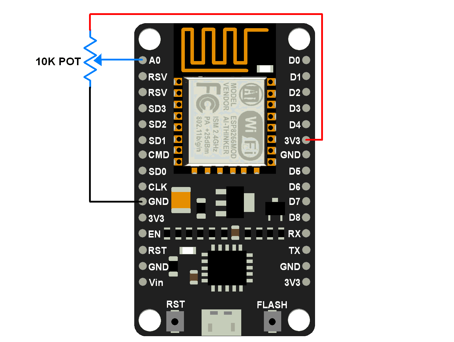
Let’s write an Arduino sketch for reading the analog voltage on the ADC pin of NodeMCU. Here we use a potentiometer to provide variable voltage from 0-3.3V on the ADC pin of Dev Kit. Connect pot as shown in the below diagram.
Potentiometer Interfacing with NodeMCU
Arduino Code for reading external voltage using NodeMCU
void setup() {
Serial.begin(9600);
}
void loop() {
Serial.print("ADC Value: ");
Serial.println(analogRead(A0));
delay(300);
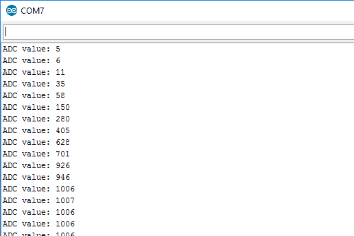
}Output window
The below figure shows the output on the serial monitor of Arduino IDE
Arduino Code for reading System voltage using NodeMCU
ADC_MODE(ADC_VCC);

void setup() {
  Serial.begin(9600);
}

void loop() {
  Serial.print("System voltage(mV): ");
  Serial.println(ESP.getVcc());
  delay(300);
}
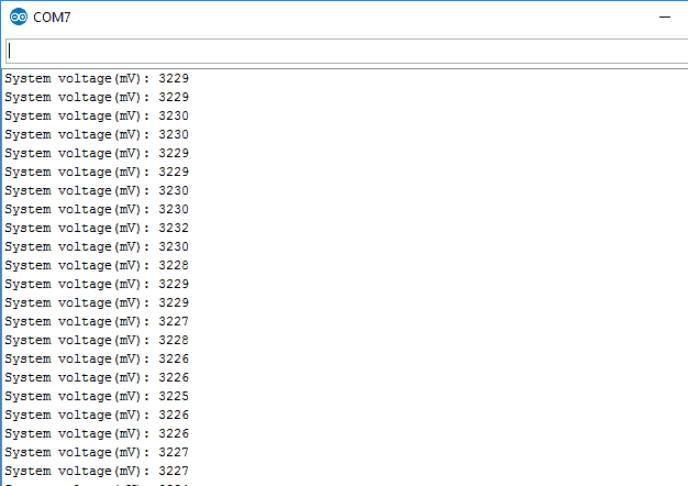
Output window
The below figure shows the serial monitor output of Arduino IDE
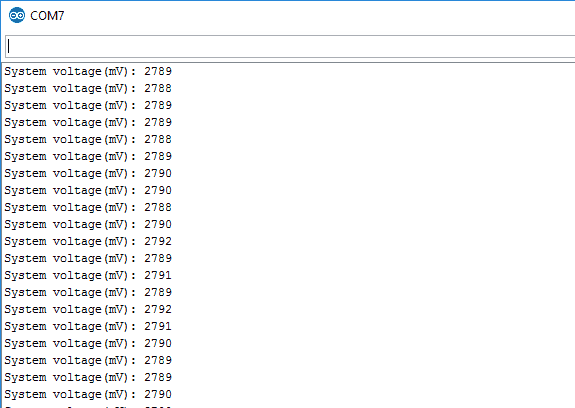
Here we found that the value measured deviates slightly from the actual value. For the external voltage, we get 5-1007 ADC value variation for 0-3.3V applied to the ADC pin on Dev Kit. And for system voltage (voltage on module), we get up to 2790 mV i.e. around 2.8V. This shows about 0.5V difference than actual i.e. 3.3V.
The issue of external voltage measurement is given at #2672 and #3168 on the ESP8266 Github page. And the issue about system voltage reading is given at #721 on the ESP8266 Github page.
According to the datasheet of ESP8266, the TOUT (ADC pin of ESP8266) pin must be dangled (floating) while measuring the power supply voltage through ADC. But on NodeMCU Dev Kit/Modules it is connected to the voltage divider network of resistors (100Kohm & 220Kohm) for the sake of external voltage range (0-3.3V) support as shown in below figure.
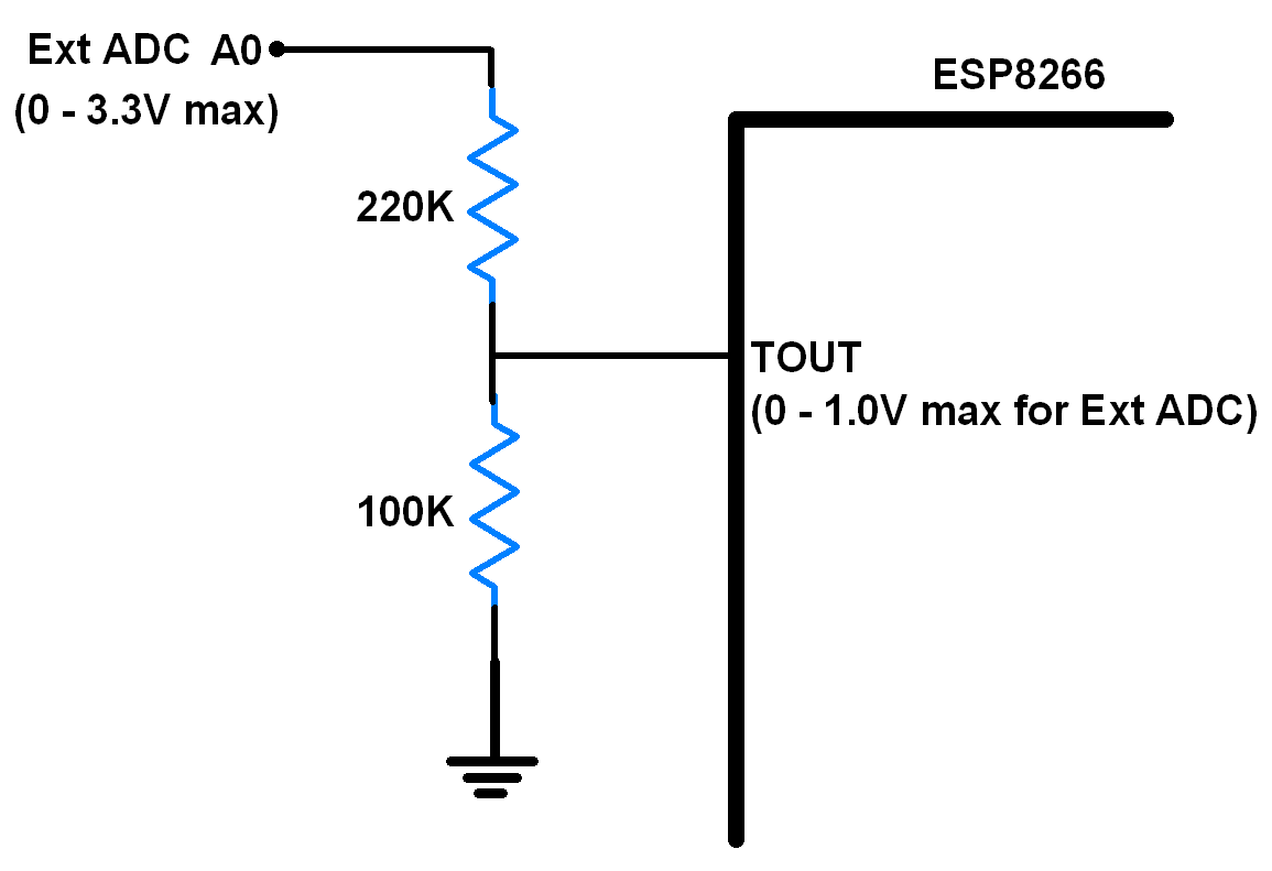
Now, if we remove the resistor divider n/w, and left the ADC pin (TOUT) floating then we can get better accuracy in the result as shown in below output window image of system voltage readings which is near to the 3.3V.
Components Used |
||
|---|---|---|
| NodeMCU NodeMCUNodeMCU |
X 1 | |
| ESP12F ESP12E |
X 1 | |