Description
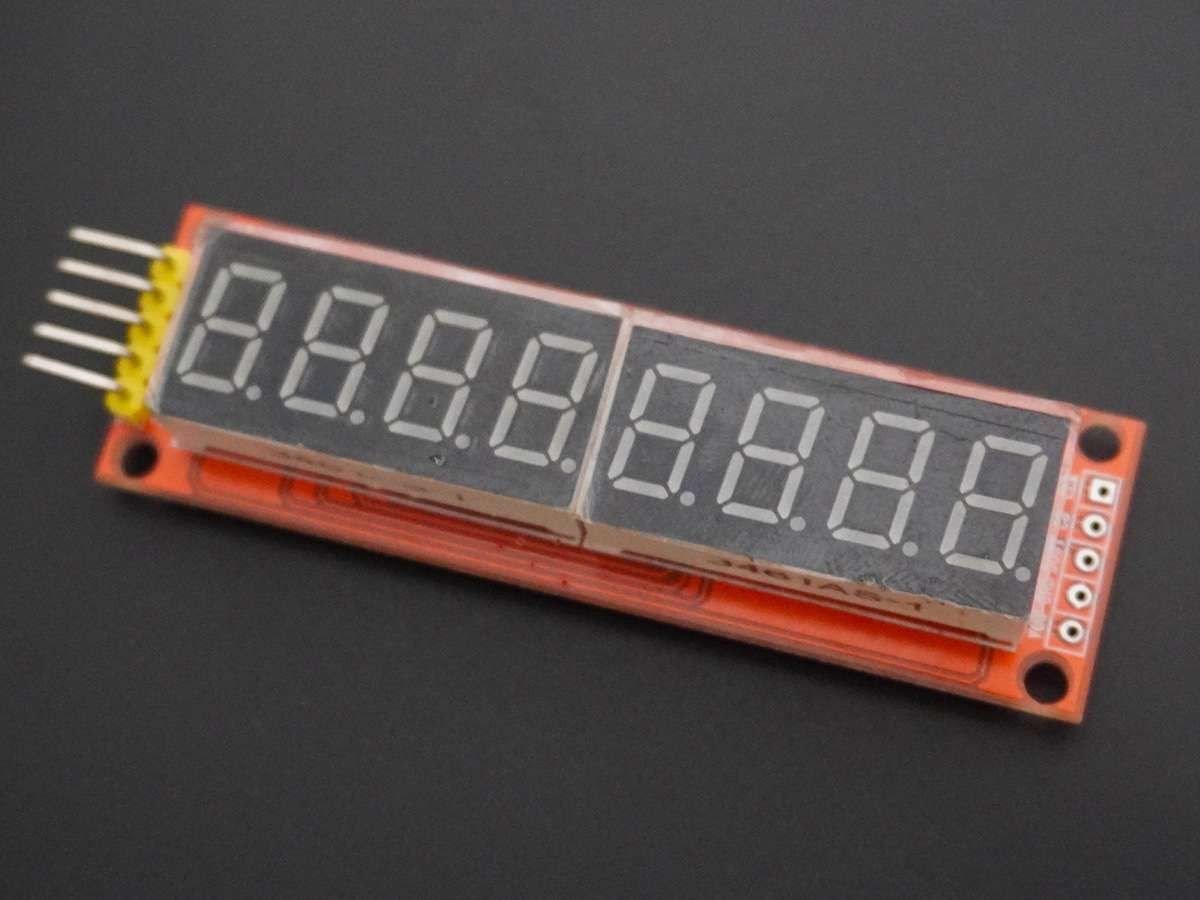

- The MAX7219 is a serially interfaced 8-digit LED display driver. It can be used to control up to 64 individual LEDs, or eight 7-segment displays.
- The MAX7219 provides a convenient and cost-effective way to interface common anode 7-segment displays with microcontrollers or other digital logic circuits.
- The module uses SPI communication for interfacing with the microcontroller.
- These modules are compact and require few pins and wires compared to using singular 7-segment displays in cascade.
MAX7219 7-Segment Display Pin Configuration
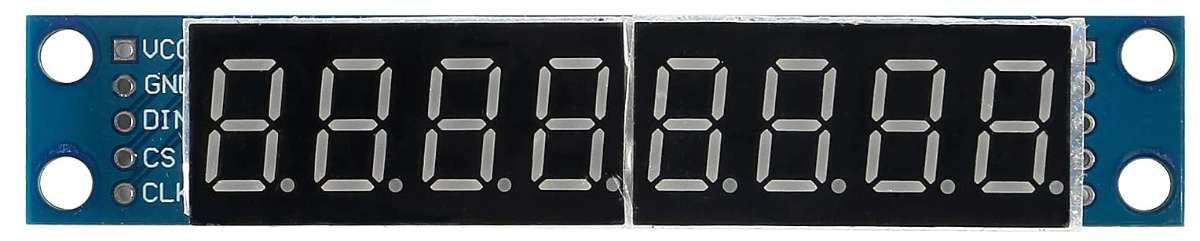
- VCC: Connected to +3.3V
- GND: Connected to the ground
- DIN: This pin is used to input data into the MAX7219. Data is clocked into the MAX7219 on the rising edge of the serial clock signal.
- CS: This pin is used to enable/disable the MAX7219. When it is LOW module is enabled and when the pin is HIGH the module is disabled.
- CLK: This pin is used to provide the serial clock signal to the MAX7219.
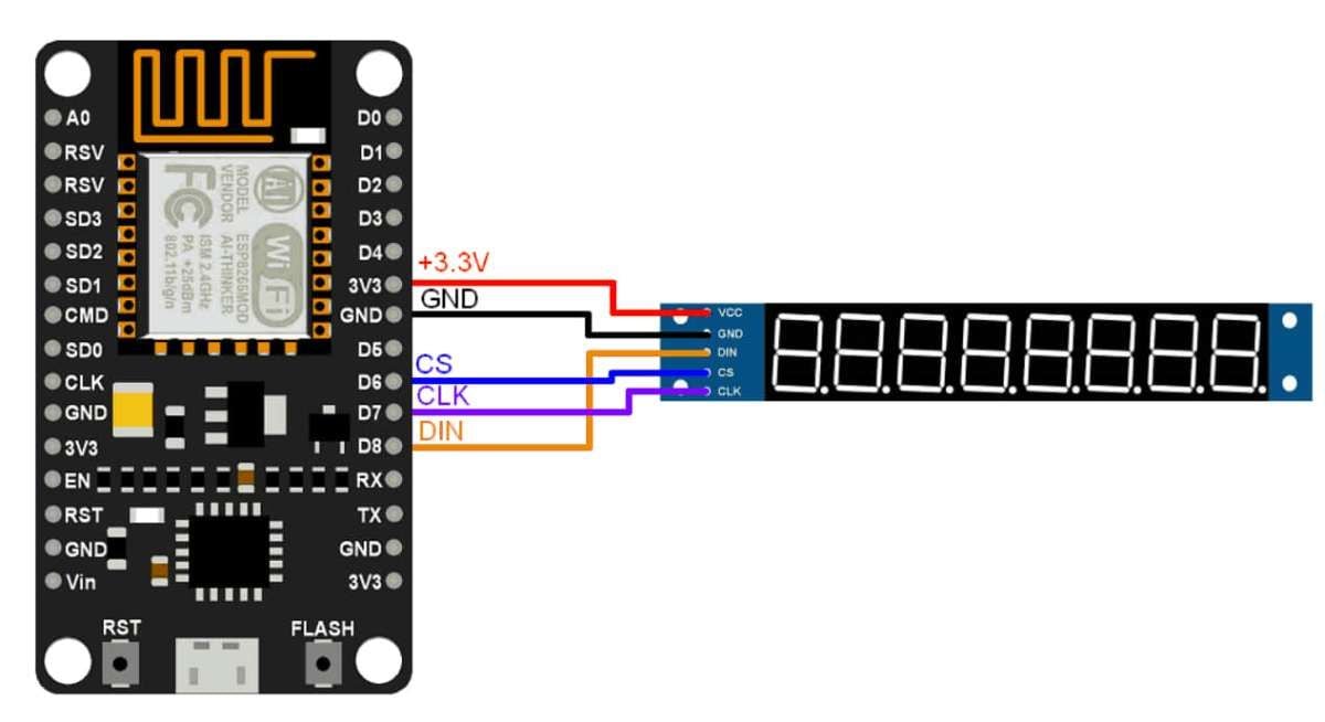
MAX7219 7-Segment Display Hardware Connection with NodeMCU
Displaying the Digits using MAX7219 7-Segment Display
Here we have used the LedController library for displaying the numbers on the 7-Segment Display.
Download the library from the below link.
https://www.arduino.cc/reference/en/libraries/ledcontroller/
Simple Code to Display the Numbers on MAX7219 7-Segment Display
/**
 * @file LCDemo7Segment.ino
 * @author Noa Sakurajin ([email protected])
 * @brief using the ledcontroller with 7-segment displays
 * @version 0.1
 * @date 2020-12-30
 *
 * @copyright Copyright (c) 2020
 *
 */

#include "LedController.hpp"
/*
 You might need to change the following 3 Variables depending on your board.
 pin D8 is connected to the DataIn
 pin D7 is connected to the CLK
 pin D6 is connected to LOAD/ChipSelect
*/
#define DIN D8
#define CS D6
#define CLK D7

/*
 Now we need a LedController Variable to work with.
 We have only a single MAX72XX so the Dimensions are 1,1.
 */
LedController<1,1> lc;

/* we always wait a bit between updates of the display */
unsigned long delaytime=1000;

void setup() {
  //Here a new LedController object is created without hardware SPI.
 lc=LedController<1,1>(DIN,CLK,CS);
  lc.setIntensity(8); /* Set the brightness to a medium values */
  lc.clearMatrix(); /* and clear the display */
}

void loop() {
  for(int i=0; i<8; i++) {
    lc.setDigit(0,i,i,false);
    delay(delaytime);
  }
  lc.clearMatrix();
  delay(delaytime);
}
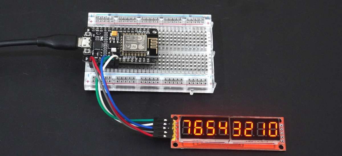
- Now upload the code in NodeMCU.
- The numbers from 0 to 7 will start displaying on the 7-Segment Display.
Output
Let’s Understand the Code
At the top, we have included the library LedController.cpp which includes functions and classes for controlling different types of LED displays, such as 7-segment displays, dot-matrix displays, or RGB LED strips.
#include "LedController.cpp"Next, we have defined the pins for NodeMCU such as,
#define DIN D8
#define CS D6
#define CLK D7
Then we created an object of the LedController class, which is instantiated with a template parameter of 1,1 to indicate that there is only one MAX7219 connected to the microcontroller.
LedController<1,1> lc;Now we will wait for a sec for the updates on the display
unsigned long delaytime=1000;
In the Setup Function, we have initialized the LedController object with the pin numbers specified by the DIN, CLK, and CS constants.
This creates a new LedController object without using hardware SPI.
And using the functions setIntensity and clearMatrix we can adjust the brightness of the display and clear the display respectively.
void setup() {
  //Here a new LedController object is created without hardware SPI.
  lc=LedController<1,1>(DIN,CLK,CS);
  lc.setIntensity(8); /* Set the brightness to a medium values */
  lc.clearMatrix(); /* and clear the display */
}
In the Loop Function, using the for loop we have repeatedly displayed the digits from 0 to 8 on the display.
For displaying we have used the setDigit function. After printing the digits, with the help of clearMatrix, we erased the digits and displayed them again.
void loop() {
  for(int i=0; i<8; i++) {
    lc.setDigit(0,i,i,false);
    delay(delaytime);
  }
  lc.clearMatrix();
  delay(delaytime);
}
Components Used |
||
|---|---|---|
| MAX7219 LED Display Driver MAX7219 is a serial input/output common cathode display driver that interfaces microprocessors to 7-segment numeric displays of up to 8 digits, bar graph displays, or 64 individual LEDs. |
X 1 | |
| NodeMCU NodeMCUNodeMCU |
X 1 | |
Downloads |
||
|---|---|---|
|
|
MAX7219_7-SegmentDisplay_NodeMCU | Download |