Introduction to GPIO
General-purpose input/output (GPIO) is a pin on an IC (Integrated Circuit). It can be either an input pin or output pin, whose behavior can be controlled at the run time.
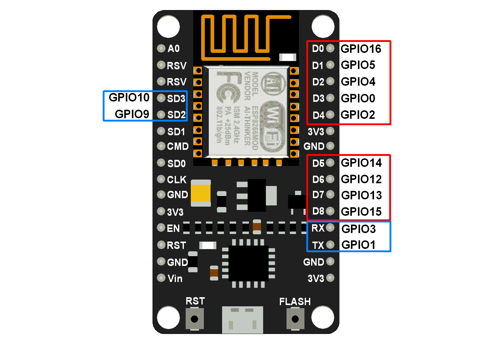
NodeMCU Development kit provides access to these GPIOs of ESP8266. The only thing to take care of is that NodeMCU Devkit pins are numbered differently than internal GPIO notations of ESP8266 as shown in the below figure and table. For example, the D0 pin on the NodeMCU Devkit is mapped to the internal GPIO pin 16 of ESP8266.
NodeMCU GPIO Pins
The below table gives NodeMCU Dev Kit IO pins and ESP8266 internal GPIO pins mapping
| Pin Names on NodeMCU Development Kit | ESP8266 Internal GPIO Pin number |
|---|---|
| D0 | GPIO16 |
| D1 | GPIO5 |
| D2 | GPIO4 |
| D3 | GPIO0 |
| D4 | GPIO2 |
| D5 | GPIO14 |
| D6 | GPIO12 |
| D7 | GPIO13 |
| D8 | GPIO15 |
| D9/RX | GPIO3 |
| D10/TX | GPIO1 |
| D11/SD2 | GPIO9 |
| D12/SD3 | GPIO10 |
The GPIO’s shown in the blue box (1, 3, 9, 10) are not commonly used for GPIO purpose on Dev Kit
ESP8266 is a system on a chip (SoC) design with components like the processor chip. The processor has around 16 GPIO lines, some of which are used internally to interface with other components of the SoC, like flash memory.
Since several lines are used internally within the ESP8266 SoC, we have about 11 GPIO pins remaining for GPIO purposes.
2 pins out of 11 are generally reserved for RX and TX in order to communicate with a host PC from which compiled object code is downloaded.
Hence finally, this leaves just 9 general-purpose I/O pins i.e. D0 to D8.
As shown in the above figure of NodeMCU Dev Kit. We can see RX, TX, SD2, SD3 pins are not commonly used as GPIOs since they are used for other internal processes. But we can try with SD3 (D12) pin which mostly likes to respond for GPIO/PWM/interrupt like functions.
Note that the D0/GPIO16 pin can be only used as GPIO read/write, no special functions are supported on it.
Example
Let’s write an Arduino sketch for LED blinking on pin D4 of NodeMCU Dev Kit.
NodeMCU LED Blinking code using Arduino IDE
uint8_t LED_Pin = D4;       // declare LED pin on NodeMCU Dev Kit

void setup() {
	pinMode(LED_Pin, OUTPUT);   // Initialize the LED pin as an output
}

void loop() {
	digitalWrite(LED_Pin, LOW); // Turn the LED on
	delay(1000);                // Wait for a second
	digitalWrite(LED_Pin, HIGH);// Turn the LED off
	delay(1000);                // Wait for a second
}
Note
Some of the GPIO pins are used while booting, so Pulling this pin HIGH or LOW can prevent NODEMCU from booting
- GPIO0: It oscillates and stabilizes HIGH after ~100ms. Boot Failure if pulled LOW
- GPIO1: LOW for ~50ms, then HIGH, Boot Failure if Pulled LOW.
- GPIO2: It oscillates and stabilize HIGH after ~100ms, Boot Failure if Pulled LOW.
- GPIO3: LOW for ~50ms, then HIGH.
- GPIO9: Pin is HIGH at Boot.
- GPIO10: Pin is HIGH at Boot.
- GPIO15: LOW, Boot failure if Pulled HIGH
- GPIO16: HIGH during Boot and Falls to ~1Volt.
Consider Pins HIGH/ LOW at boot, if you are connecting any peripheral device as output i.e. Relay, Optocouplers, transistors or any such drivers may create a problem.
Built-in LED on NODEMCU: GPIO2 i.e. D4 pin, even some board have LED on GPIO16.
For detailed reference on GPIO behavior click here.
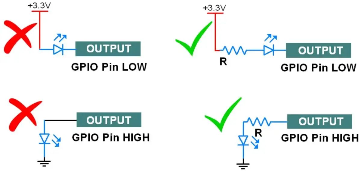
GPIO Cautions:
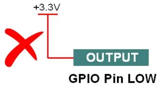
- If the GPIO pin defines as an OUTPUT LOW then don’t connect this pin to VCC, it will get short circuit and large current flow will damage your controller or GPIO pin.
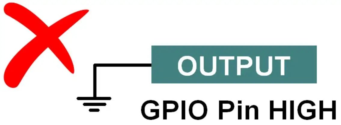
- If the GPIO Pin defines as an OUTPUT HIGH then don’t connect this pin to Ground, it will draw large current which will damage your controller or GPIO pin.
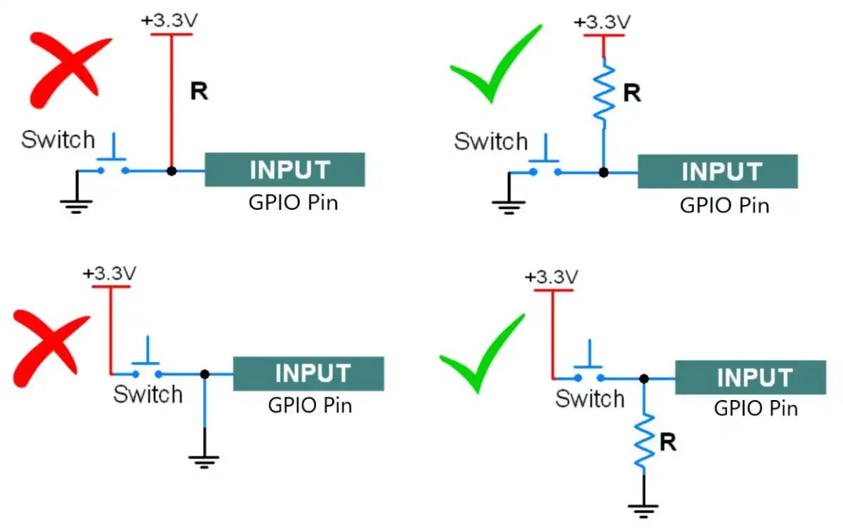
- For switch connection always use a pull-up or pull-down (based on your coding logic). Always use pull UP/pull down resistor inside the microcontroller or connect an external resistor.
- Don’t connect the direct VCC pin to the GPIO pins, otherwise it will short the power supply when you press the switch.
- Kindly check following scenarios:
- While interfacing the led always connect a series resistor to limit the current, otherwise LED will burn.
Components Used |
||
|---|---|---|
| NodeMCU NodeMCUNodeMCU |
X 1 | |
| ESP12F ESP12E |
X 1 | |