Introduction to Watchdog Timer
- Watchdog Timer (WDT) can be helpful to automatically reset the system whenever a timeout occurs.
- A system reset is required for preventing the failure of the system in a situation of a hardware fault or program error.
- There are countless applications where the system cannot afford to get stuck at a point (not even for a small duration of time). For example, in a radar system, if the system hangs for 5 minutes, it can result in serious repercussions (an enemy plane or missile may go undetected resulting in huge losses).
- The system should be robust enough to automatically detect the failures quickly and reset itself in order to recover from the failures and function normally without errors.
- One can manually reset the system to recover from errors. But it is not always feasible to manually reset the system, especially once it has been deployed.
- To overcome such problems, a watchdog timer is necessary to automatically reset the system without human intervention.
How does Watchdog Timer work?
- The watchdog timer is loaded with a timeout period which is dependent on the application.
- The watchdog timer starts its counting independent of a system clock i.e. it has a separate internal oscillator to work independently of a system clock.
- The watchdog timer cleared through software each time before the timeout period occurs.
- Whenever software failed to clear the watchdog timer before its timeout period, the watchdog timer resets the system.
- For this purpose, a watchdog timer is used to overcome software failures in real-time applications.
- The watchdog timer is also used to wake up the microcontroller from sleep mode.
Inside of PIC18F4550 Watchdog Timer
- In PIC18F4550, the watchdog timer uses a different 31 kHz INTRC clock and it is independent of a system clock.
- Watchdog Timer can be enabled in two ways through Configuration Register (CONFIG2H) and through WDTCON Register.
- CONFIG2H has a WDTEN bit to enable/disable the watchdog timer.
- WDTCON (WDT control register) has the SWDTEN bit which is used to enable/disable the WDT through software.
Below fig. shows how WDT operates in PIC18F4550.
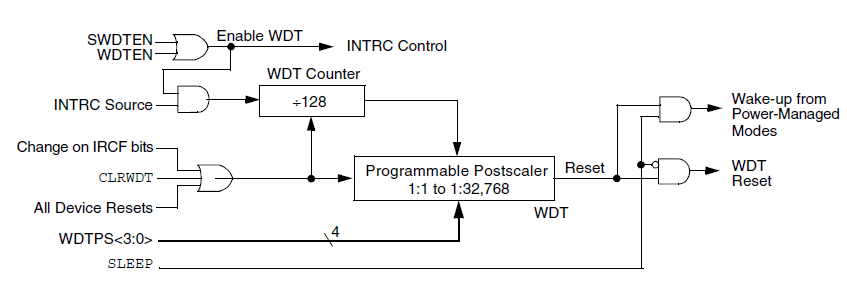
- When WDT is enabled, 31 kHz INTRC source gets initialized and provides a clock for the watchdog timer.
- This clock is then divided by 128 (pre-scaler). This pre-scaler gives a nominal time-out period of 4 ms.
- PIC18F4550 also has a programmable Post-scaler which helps to divide down the WDT pre-scaler output and increase the time-out periods. So now we can vary the time-out period in the range of 4ms to 131.072 sec (2.18 min) using Post-scaler.
Enabling and Disabling WDT
There are two ways to enable or disable the WDT which are given as follows:
1. Through Configuration Register:
CONFIG2H Register: Configuration Register 2 High

Bit 0 – WDTEN: Watchdog Timer Enable bit
0 = Disables WDT (possible to enable WDT through SWDTEN)
1 = Enables WDT
Bit 4:1 – WDTPS3:WDTPS0: Watchdog Timer Post-scale select bit
1111 = 1:32768
1110 = 1:16384
1101 = 1:8192
1100 = 1:4096
1011 = 1:2048
1010 = 1:1024
1001 = 1:512
1000 = 1:256
0111 = 1:128
0110 = 1:64
0101 = 1:32
0100 = 1:16
0011 = 1:8
0010 = 1:4
0001 = 1:2
0000 = 1:1
2. Through WDTCON Register:
WDTCON Register: Watchdog Timer Control Register

Bit 0 – SWDTEN: Software Controlled Watchdog Timer Enable bit
0 = Disable Watchdog Timer
1 = Enable Watchdog Timer
This software controlled watchdog timer can enable watchdog timer only if configuration bit has disabled the WDT.
If the WDTEN (configuration bit) is enabled, then SWDTEN has no effect.
How to calculate the WDT Timeout Period?
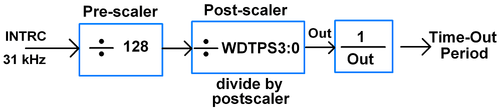
E.g.
If we configure Post-scaler WDTPS3:WDTPS0 = 1001 i.e. 512 is Post-scaler then,
31 kHz/128 = 242.1875
Now,
Out = 242.1875/512 = 0.473
Time-out period = 1/0.473 = 2.11 sec
Program
- There are two ways for using Watchdog Timer in PIC18F4550. Here, we blink LEDs continuously and they stuck in between.
- Then WDT resets the PIC18F4550 microcontroller after a specific timeout period which starts blinking of LED again. When WDT reset occurs it displayed on LCD16x2.
Note: TO’ bit in RCON register gives the status of WDT time-out occurrence.
Configuration Register Controlled WDT
/*
   Watchdog Timer in PIC18F4550
   http://www.electronicwings.com
 */


#include "Configuration_Header_File.h"
#include "LCD_16x2_8-bit_Header_File.h"
#include <pic18f4550.h>

#pragma config WDT = ON         /* Watchdog Timer Enable bit (WDT enabled)*/
#pragma config WDTPS = 256      /* Watchdog Timer Postscale Select bits */


void Dummy_Stuck();

#define LED LATB
#define PORT_Direction TRISB

void main(void)
{
    int count;
    PORT_Direction = 0;         /* set port as output port */
    OSCCON = 0x72;              /* use internal oscillator frequency, 8 MHz*/
    LCD_Init();
    if(!RCONbits.TO)            /* check for WDT reset occurense */
        LCD_String_xy(1,0,"WDT Reset");
    MSdelay(1000);
    LCD_Clear();
    count = 0;
    LED = 0;
    while(1)
    {
        LED = ~LED;             /* Toggle LED */
        MSdelay(100);
        CLRWDT();               /* Clear Watchdog Timer */
        count++;
        if(count>20)
            Dummy_Stuck();      /* Dummy Stuck loop function */
    }
}


void Dummy_Stuck()
{
    while(1);                   /* wait till watchdog timeout and then reset system */
}
Software Controlled WDT
/*
   Watchdog Timer in PIC18F4550
   http://www.electronicwings.com
 */


#include "Configuration_Header_File.h"
#include "LCD_16x2_8-bit_Header_File.h"
#include <pic18f4550.h>

#pragma config WDT = OFF         /* Watchdog Timer Enable bit (WDT disabled (control is placed on the SWDTEN bit))*/
#pragma config WDTPS = 512       /* Watchdog Timer Postscale Select bits */


void Dummy_Stuck();

#define LED LATB
#define PORT_Direction TRISB

void main(void)
{
    int count;
    PORT_Direction = 0;         /* set port as output port */
    OSCCON = 0x72;              /* use internal oscillator frequency, 8 MHz*/
    LCD_Init();
    WDTCONbits.SWDTEN = 1;      /* enable software controlled watchdog timer*/
    if(!RCONbits.TO)            /* check for WDT reset occurrence */
        LCD_String_xy(1,0,"WDT Reset");
    MSdelay(1000);
    LCD_Clear();
    count = 0;
    LED = 0;
    while(1)
    {
        LED = ~LED;             /* Toggle LED */
        MSdelay(100);
        CLRWDT();               /* Clear Watchdog Timer */
        count++;
        if(count>20)
            Dummy_Stuck();      /* Dummy Stuck loop function */
    }
}

void Dummy_Stuck()
{
    while(1);                   /* wait till watchdog timeout and then reset system */
}
Video
Components Used |
||
|---|---|---|
| PICKit 4 MPLAB PICKit 4 MPLAB |
X 1 | |
| PIC18f4550 PIC18f4550 |
X 1 | |
| LCD16x2 Display LCD16x2 Display |
X 1 | |