Introduction
Several devices such as GPS, GSM, RFID, sensors, etc need to communicate with the PIC microcontroller for transmitting or receiving information. To communicate with the PIC microcontroller, several communication protocols are used such as RS232, SPI, I2C, CAN, etc. Basically, a protocol is a set of rules agreed by both, the sender and the receiver, on -
- How the data is packed?
- How many bits constitute a character?
- When the data begins and ends?
PIC18F4550 has an in-built USART module which is useful for serial communication. With the help of USART, we can send/receive data to a computer or other devices. USART is also used in interfacing PIC with various modules like Wi-Fi (ESP8266), Bluetooth, GPS, GSM, etc.
We will see how the communication is established between PIC microcontroller and PC through USART using RS232 protocol. We will also see how to communicate with laptops, which do not have an RS232 DB9 port, and instead use a USB port.
Let us start with the serial communication using PIC18F4550.
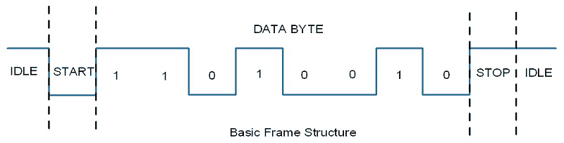
Asynchronous Communication: PIC18F4550 has a built-in asynchronous receiver-transmitter. Asynchronous means each character (data byte) is placed in between the start and stop bits. The start bit is always 0 (low) and the stop bit is always 1 (high).
Bit Rate & Baud Rate: The rate of data transfer in serial data communication is stated in bps (bits per second). Another widely used terminology for bps is baud rate; means, a number of changes in signal per second. Here the signal is in bits, therefore bit rate = baud rate.
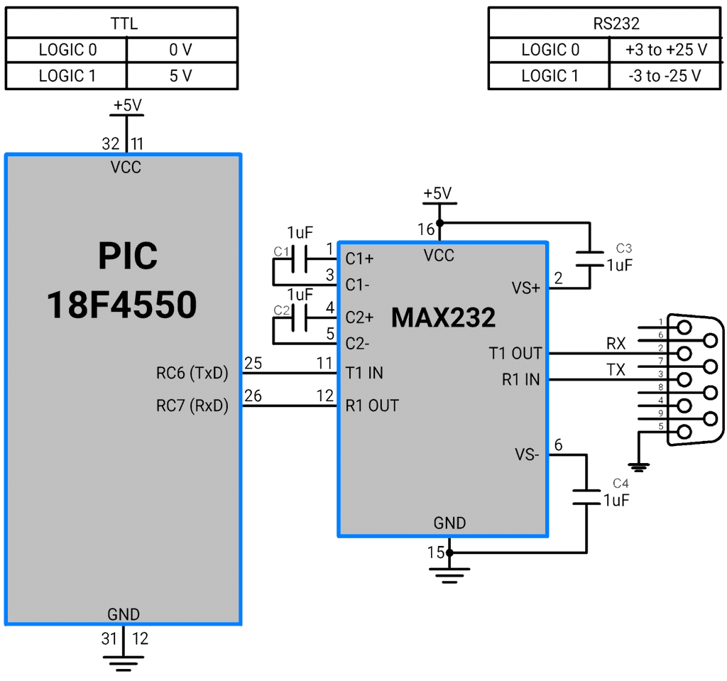
Interface: Although there are many pins in the DB9 connector, we do not need all. We only use pins RX, TX, and GND.
Level Conversion
Convert PIC18F TTL levels to RS232 levels and vice-versa
PC has RS232 levels whereas the PIC microcontroller has TTL levels. The RS232 has different voltage levels for logic 0 and 1. To make it compatible with the PIC TTL voltage levels, we have to use a MAX232 IC.
Baud Rate Calculation
How to Calculate the Baud Rate in PIC18F4550?
a value that will be loaded into the SPBRG register (16-bit) of the PIC18F4550 to get the desired baud rate. The value of SPBRG for the desired baud rate is calculated as,
E.g.
Suppose, Fosc = 8 MHz and Baud Rate = 9600 bps
Then, SPBRG=((8 MHz)/(64 ×9600))-1
SPBRG = ( 8 MHz / 64 × 9600) - 1
Therefore, SPBRG = 12
The above formula depends on the BRGH bit in the TXSTA register.
Let’s see the TXSTA register, which is used for transmission setting, in detail as follows
TXSTA: Transmit Status and Control Register

TXEN: Transmit Enable Bit
1 = Enable the transmission
0 = Disable the transmission
BRGH: High Baud Rate select bit
0 = Low speed
1 = High speed
Load the calculated value directly to the SPBRG register.
CSRC bit is not used for asynchronous communication.
TX9 : 9th Transmit Enable Bit
0 = Select 8-bit transmission
1 = Select 9-bit transmission
SYNC : USART Mode Select Bit
0 = Asynchronous mode
1 = Synchronous mode
SENDB : Send Break Character bit
1 = Send Sync Break on next transmission (cleared by hardware upon completion)
0 = Sync Break transmission completed
TRMT : Transmit Shift Register Status Bit
0 = TSR full
1 = TSR empty
TX9D: 9th bit of transmitting data
Can be Address / Data bit or a parity bit.
In PIC18F4550, the RCSTA register is used for serial data receive settings.
RCSTA: Receive Control and Status Register

SPEN: Serial Port Enable
1= Enable Serial Port for communication
0 = Disable Serial Port for communication
RX9 : 9-bit Receive Enable bit
1 = Enable 9-bit reception
0 = Enable 8-bit reception
Generally, we use 8-bit reception
SREN: Single Receive Enable bit
Not used
CREN: Continuous Receive Enable bit
1 = Enable receiver for continuous reception of data byte
0 = Disable receiver
ADDEN: Address Detect Enable bit
Asynchronous mode 9-bit (RX9 = 1)
1 = Enable address detection, enable interrupt, and load the receive buffer when the RSR bit is set.
0 = Disable address detection, all bytes are received and the ninth bit can be used as a parity bit.
Asynchronous mode 9-bit (RX9 = 0)
Don’t care (any 0 or 1)
FERR: Framing Error bit
1 = Framing error (can be updated by reading the RCREG register and receiving the next valid byte)
0 = No framing error
OERR: Overrun Error bit
1 = Overrun error can be cleared by clearing bit CREN.
0 = No overrun error
RX9D: 9th bit of the Receiving Data
This can be address/data bit or a parity bit and must be calculated by user firmware.
Data Buffer and Interrupt Flag for Serial Communication
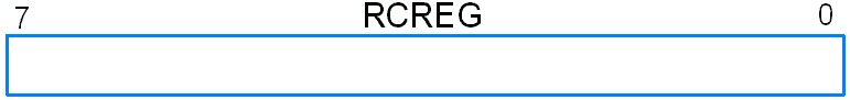
For transmitting data and reception of data TXREG and RCREG 8-bit data registers are allocated in PIC18F4550 respectively.
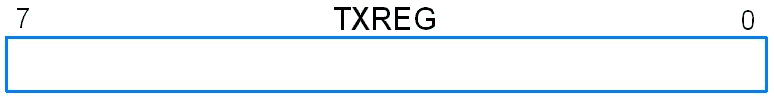
- When we have to transmit data, we directly copy that data to the TXREG register. After completing the transmission of 8-bit data, the TXIF interrupt flag is generated.
- This TXIF (transmit interrupt flag) is located in the PIR1 register. TXIF flag is set when the 8-bit data is transmitted. Then, the buffer is ready to receive another data for transmission.
- Also, RCIF (receive interrupt flag) is located in the PIR1 register. When this flag is set, it indicates that the complete data byte is received by the RCREG register. Read the RCREG register immediately. Now, the RCREG register is ready to receive another data.
- When the RCIF flag is not set, the PIC microcontroller has to wait for the reception of the complete data byte.
Steps for Programming PIC18F4550 USART
Initialization
1. Initialize the Baud Rate by loading a value into the SPBRG register.
2. Then set bit SPEN in the RCSTA for enabling Serial Port.
3. Then set bit BRGH in the TXSTA for low or high speed.
4. Also clear bit SYNC in the TXSTA register for asynchronous communication.
5. Set bit TXEN in the TXSTA register to enable transmission.
6. Set bit CREN in the RCSTA register to enable reception.
#define F_CPU 8000000/64

void USART_Init(long baud_rate)
{
    float temp;
    TRISC6=0;		/* Make Tx pin as output*/
    TRISC7=1;  		/* Make Rx pin as input*/

    /* Baud rate=9600, SPBRG = (F_CPU /(64*9600))-1*/
    temp= (( (float) (F_CPU) / (float) baud_rate ) - 1);
    SPBRG = (int) temp;

    TXSTA = 0x20;  	/* Enable Transmit(TX) */
    RCSTA = 0x90;  	/* Enable Receive(RX) & Serial */
}
Transmit mode
1. Copy the data which we want to transmit into the TXREG register.
2. Monitor the flag TXIF which is set when the transmission is completed.
Char USART_TransmitChar (char out)
{
   while (TXIF == 0);	/* Wait for transmit interrupt flag*/
   TXREG = out;  	/* Write char data to transmit register */
}
Receive mode
1. Monitor the flag RCIF until it is set to 1, which indicates a complete 1 byte is received in the RCREG register.
2. Also, check for OERR bit. If it is set then disable and enable CREN.
3. Then, read the RCREG register immediately to avoid overflow.
Char USART_ReceiveChar()
{
    while(RCIF==0);      /*wait for receive interrupt flag*/
    if(RCSTAbits.OERR)
    {
        CREN = 0;
        NOP();
        CREN=1;
    }
    return(RCREG);       /*received in RCREG register and return to main program */
}
Application
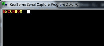
Let’s create a simple application in which we will generate an echo of characters where the characters will be transmitted serially from PC to PIC18F4550 and returned back from PIC18F4550 to PC.
/*
  Generating an echo on PC using PIC18F4550 USART communication module
  http:://www.electronicwings.com
*/

#include <pic18f4550.h>
#include "Configuration_Header_File.h"
#include "LCD_16x2_8-bit_Header_File.h"

void USART_Init(long);
void USART_TxChar(char);
char USART_RxChar();

#define F_CPU 8000000/64

#define Baud_value (((float)(F_CPU)/(float)baud_rate)-1)

/************************CODE FOR ECHO GENERATION USING USART*****************/
void main()
{
    OSCCON=0x72;
    char data_in;
    LCD_Init();               /*Initialize 16x2 LCD */
    USART_Init(9600);         /*initialize USART operation with 9600 baud rate*/
    MSdelay(50);
    while(1)
    {
        data_in=USART_RxChar();
        LCD_Char(data_in);
        USART_TxChar(data_in);
    }

}

/*****************************USART Initialization*******************************/
void USART_Init(long baud_rate)
{
    float temp;
    TRISC6=0;                       /*Make Tx pin as output*/
    TRISC7=1;                       /*Make Rx pin as input*/
    temp=Baud_value;
    SPBRG=(int)temp;                /*baud rate=9600, SPBRG = (F_CPU /(64*9600))-1*/
    TXSTA=0x20;                     /*Transmit Enable(TX) enable*/
    RCSTA=0x90;                     /*Receive Enable(RX) enable and serial port enable */
}
/******************TRANSMIT FUNCTION*****************************************/
void USART_TxChar(char out)
{
        while(TXIF==0);            /*wait for transmit interrupt flag*/
        TXREG=out;                 /*transmit data via TXREG register*/
}
/*******************RECEIVE FUNCTION*****************************************/
char USART_RxChar()
{

while(RCIF==0);       /*wait for receive interrupt flag*/
    if(RCSTAbits.OERR)
    {
        CREN = 0;
        NOP();
        CREN=1;
    }
    return(RCREG);   /*receive data is stored in RCREG register and return */
}
Output
USART Communication using Interrupt Service Routine (ISR)
- The above USART communication is done by polling the interrupt flag continuously.
- However, polling the interrupt flag increases power consumption in the microcontroller, and also it is unable to perform other tasks as the interrupt polling is executing continuously.
- Interrupt Service Routine (ISR) executes the application code whenever an interrupt occurs.
- And if the interrupt does not occur, the microcontroller controller can execute other tasks.
To make use of USART ISR in PIC18F4550, GIE (Global Interrupt Enable), PEIE (Peripheral Interrupt Enable) needs to be enabled along with RCIE (Receive Interrupt Enable) and TXIE (Transmit Interrupt Enable).
Steps for Programming PIC18F4550 USART using Interrupt
Initialization
- Initialize the Baud Rate by loading value to the SPBRG register.
- Then set bit SPEN in the RCSTA for Serial Port enable.
- Then set bit BRGH in the TXSTA for low or high speed.
- Also, clear bit SYNC in the TXSTA registers for asynchronous communication.
- Set bit TXEN in the TXSTA register to enable transmission.
- Set bit CREN in the RCSTA register to enable reception.
Enable GIE, PEIE, RCIE and TXIE for ISR.
#define F_CPU 8000000/64

void USART_Init(long baud_rate)
{
    float temp;
    TRISC6=0;		/* Make Tx pin as output*/
    TRISC7=1;		/* Make Rx pin as input*/
    temp=(( (float) (F_CPU) / (float) baud_rate) - 1);
    SPBRG = (int) temp;	/* Baud rate=9600 SPBRG=(F_CPU /(64*9600))-1*/
    TXSTA = 0x20;	/* TX enable; */
    RCSTA = 0x90;	/* RX enable and serial port enable*/
    INTCONbits.GIE = 1;	/* Enable Global Interrupt */
    INTCONbits.PEIE = 1;/* Enable Peripheral Interrupt */
    PIE1bits.RCIE = 1;	/* Enable Receive Interrupt*/
    PIE1bits.TXIE = 1;	/* Enable Transmit Interrupt*/
}
Application Code for ECHO using ISR
/*
  Generating an echo on PC using PIC18F4550 USART ISR
  http://www.electronicwings.com
*/
#include <pic18f4550.h>
#include "Configuration_Header_File.h"
#include "LCD_16x2_8-bit_Header_File.h"

void USART_Init(long);

#define F_CPU 8000000/64
char out;

void main()
{
    OSCCON=0x72;
    LCD_Init();
    USART_Init(9600);
    LCD_String_xy(1,0,"Receive");
    LCD_Command(0xC0);
    while(1);
}

void USART_Init(long baud_rate)
{
    float temp;
    TRISC6=0;		/* Make Tx pin as output */
    TRISC7=1;		/* Make Rx pin as input */
    temp=(( (float) (F_CPU) / (float) baud_rate) - 1);
    SPBRG=(int)temp;	/* Baud rate=9600 SPBRG=(F_CPU /(64*9600))-1 */
    TXSTA=0x20;		/* TX enable; */
    RCSTA=0x90;		/* RX enable and serial port enable */
    INTCONbits.GIE=1;	/* Enable Global Interrupt */
    INTCONbits.PEIE=1;	/* Enable Peripheral Interrupt */
    PIE1bits.RCIE=1;	/* Enable Receive Interrupt */
    PIE1bits.TXIE=1;	/* Enable Transmit Interrupt */
}


void interrupt ISR()
{
      while(RCIF==0);
      out=RCREG;	/* Copy received data from RCREG register */
      LCD_Char(out);
      while(TXIF==0);
      TXREG=out;	/* Transmit received(ECHO) to TXREG register */
}
Components Used |
||
|---|---|---|
| PICKit 4 MPLAB PICKit 4 MPLAB |
X 1 | |
| PIC18f4550 PIC18f4550 |
X 1 | |
| MAX232 RS-232 Drivers MAX232 RS-232 Drivers |
X 1 | |
| USB to Serial Converter CP2104 USB to Serial Converter CP2104 |
X 1 | |
Downloads |
||
|---|---|---|
|
|
PIC18F4550 USART Communication Project File | Download |