Introduction
Input Capture is widely used in many applications such as:
- Capturing the arrival time of an event
- Measuring pulse width
- Measuring period
An event can be represented by the rising and falling edges of a pulse.
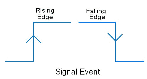
The time of an event occurrence can be recorded by latching the count when an edge is detected (rising or falling). This can be done using input capture mode in the microcontrollers.
PIC18F4550 has an in-built CCP (Capture / Compare / PWM) module which has input capture mode. The input capture of the signal has applications like finding frequency, calculating the duty cycle of the input signal, etc.
Let us see the capture mode in PIC microcontroller 18F4550.
PIC18F4550 has two CCP modules -
- CCP1
- CCP2
Here, we will be discussing the CCP1 module.
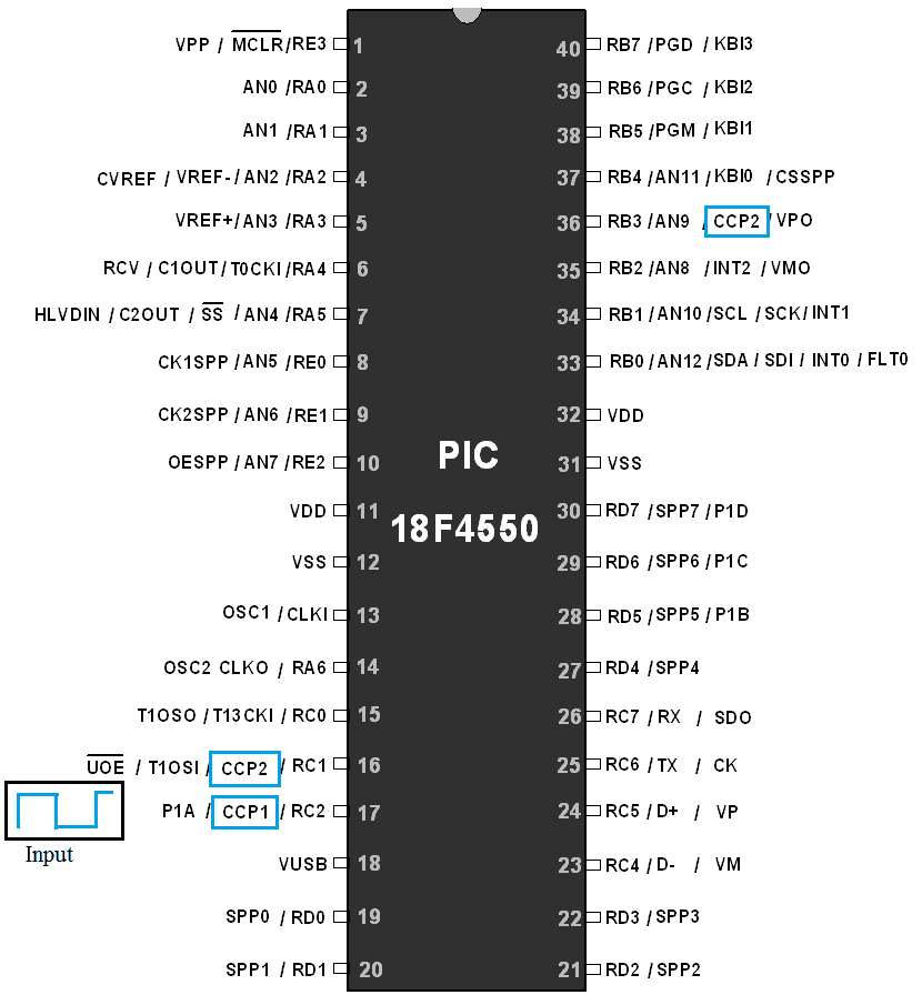
In capture mode, the input pulse should be connected to CCP1 which is multiplexed with PORTC.2 (RC2) as shown below, and configure it as the input pin.
PIC18F4550 Capture Pins
CCP1 module is able to use only the following two timers
- Timer1
- Timer3
Working of Capture Mode
Now, how the capture mode works?
- Timer1 or Timer3 are initialized to count the value in the capture operation.
- T3CON register is used for selecting the Timer1 / Timer3 for input capture shown above.
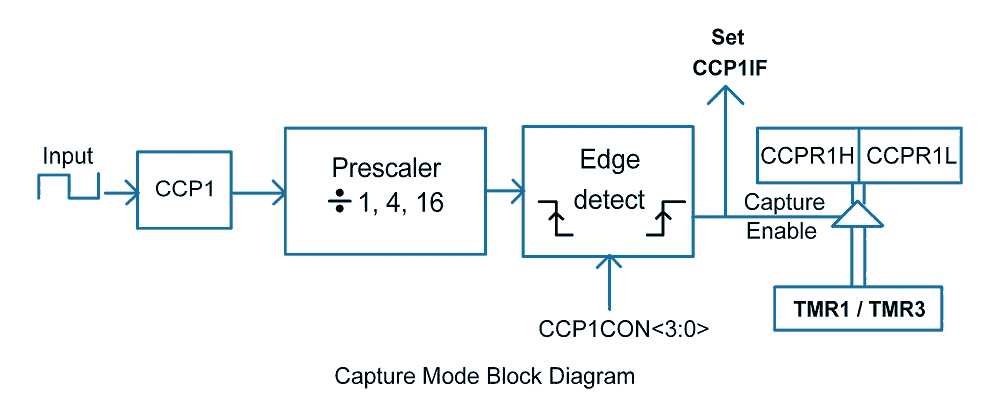
- When the rising or falling edge is detected at the CCP1 pin, the interrupt flag CCP1IF bit is set. It is cleared through software.
- When an interrupt occurs, the value of the timer is copied into CCP register CCPR1 (CCPR1H and CCPR1L), and by looking at this value we are able to find the arrival time of that event.
Capture Mode (CCP) Registers
In PIC18F4550, different registers are used for capture mode.
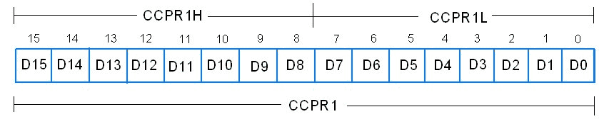
1. CCPR1 Register is a 16-bit event capture register in which the event captured by timer1 or timer3 i.e. TMR1 or TMR3 register is copied. This is done by the hardware itself. CCPR1L register and CCPR1H register are the two 8-bit registers that are used for lower and higher byte storage, respectively.
2. CCP1CON Register: CCP Control Register
This is an 8-bit register used to select the capture mode. Let’s see the bit configuration of this register.

CCP1M3 : CCP1M0: CCP1 Mode Select bits
0100 = Capture mode is selected for every falling edge detected.
0101 = Capture mode is selected for every rising edge detected.
0110 = Capture mode is selected for every 4th rising edge detected.
0111 = Capture mode is selected for every 16th rising edge detected.
And the other combinations of these bits are used for Compare and PWM mode.
DCxB1 and DCxB0 are used for PWM mode only.
CCP1IF Interrupt Flag
- After a capture event occurs, the interrupt flag is set.
- This interrupt flag is CCP1IF (CCP interrupt flag) which is located in the PIR1 register. The PIR1 register is shown below.
PIR1 Register: Peripheral Interrupt Register

CCP1IF :
1 = TMR1 or TMR3 register capture occurred (at falling or rising edge of pulse)
0 = No TMR1 or TMR3 capture occurred.
We need to enable this (CCP1IF) flag by enabling the CCP1IE bit (CCP Interrupt enable bit) in the PIE1 register.
PIE1 Register: Peripheral Interrupt Enable

T3CON Register: Timer3 Control and Status Register
T3CON register is used for selecting a timer for the capture mode. This is shown below

T3CCP2: T3CCP1 (bit 6 and bit 3)
These two bits in combination are used for Timer and Capture mode selection.
00 = Timer1 is the capture/compare clock source for both the CCP modules.
01 = Timer3 is the capture / compare clock source for the CCP2,
Timer1 is the capture / compare clock source for the CCP1
1x = Timer3 is the capture / compare clock source for both the CCP modules.
RD16 :
This bit is used to specify that the Timer3 register is 16-bit (TMR3) or two 8-bit (TMR3H and TMR3L).
RD16 = 1, Enable one 16-bit register.
RD16 = 0, Enable two 8-bit registers.
The setting of this bit is required only when we select Timer3 for the capture mode.
Otherwise, RD16 in T1CON register is used for Timer1.
Steps for Programming Capture (CCP) Mode
Initialization of PIC18F4550 Capture mode
- Initialize the CCPCON1 register for capturing the rising or falling edge.
- Configure the CCP1 pin as an input pin.
- If you are using Timer3, then configure the T3CON register to select Timer3 for input capture; otherwise, Timer1 is a default.
- Also, set the value of the T1CON or T3CON register for deciding whether the timer register should be two 8-bit (TMRxL and TMRxH) or 16-bit (TMRx).
- Set CCPR1 and TMR3 / TMR1 register to 0.
Note: ’x’ is for 1 or 3.
CCP1CON = 0x05;	/* Capture mode is selected for detecting rising edge */
CCPR1 = 0x00;	/* Clear CCPR1 register for counting*/
T1CON = 0x80;	/* Enable 16-bit TMR1 register, no pre-scale,use internal clock, timer OFF */
Capture Operation
- Make timer ON.
- Monitor until CCP1IF flag==1, which is set when capture occurs.
- Copy the value of the CCPR1 register to any data variable and get a time of event occurrence.
Frequency Measurement using PIC18F4550 Code
Let’s design an application using PIC18F4550 in which we will measure the Frequency of the input signal and display it on 16x2 LCD. The input signal is connected to the CCP1 (RC2) pin for frequency measurement.
/*
   Frequency Measurement using Input Capture Mode in PIC18F4550
   http://www.electronicwings.com
*/
#include <stdio.h>
#include <stdlib.h>
#include <p18f4550.h>
#include "osc_config.h"
#include "LCD_8bit_file.h"
#include <string.h>

#define f_timer 2000000

void main()
{
    unsigned long signal_period,data1,data2;
    unsigned long frequency_Hz[20];
    float Frequency;
    TRISCbits.TRISC2=1;
    OSCCON=0x72;        /* set internal clock to 8MHz */
    LCD_Init();
    memset(frequency_Hz,0,20);
    LCD_String_xy(0,1,"Pulse");

    PIE1bits.CCP1IE=1;
    PIR1bits.CCP1IF=0;
    CCP1CON=0x05;       /* Capture mode is selected for detecting Rising edge */
    CCPR1=0x00;         /*CCPR1 is capture count Register which is cleared initially*/
    TMR1IF=0;
    T1CON=0x80;         /* Enable 16-bit TMR1 Register,No pre-scale,use internal clock,Timer OFF */
    TMR1=0;
	TMR1ON=1; /* Turn-On Timer1 */
    while(1)
    {
        while(!(PIR1bits.CCP1IF));  /*Wait for Interrupt flag which is generated when edge is detected*/
        PIR1bits.CCP1IF=0;
        data1 = CCPR1;              /*Copy count of 1st edge detected*/

        while(!(PIR1bits.CCP1IF));  /*Wait for Interrupt flag which is generated when edge is detected*/
        PIR1bits.CCP1IF=0;
        data2 = CCPR1;              /*Copy count of 2nd edge detected*/

        if(data1 < data2)
           {

            /*Calculation for Frequency Measurement*/
            signal_period = data2 - data1;
            Frequency = ((float)f_timer / (float)signal_period); /*Count for 1 cycle*0.5us gives period */
            sprintf(frequency_Hz,"%.3f  ",Frequency);

            LCD_String_xy(2,0,frequency_Hz);

            }
        TMR1=0;
        memset(frequency_Hz,0,20);
    }
}
Video
Components Used |
||
|---|---|---|
| PICKit 4 MPLAB PICKit 4 MPLAB |
X 1 | |
| PIC18f4550 PIC18f4550 |
X 1 | |
| LCD16x2 Display LCD16x2 Display |
X 1 | |