Overview of XBee
XBee (ZigBee) radios are based on IEEE 802.15.4 (technical standard which defines the operation of low-rate wireless personal area networks (LR-WPANs)) standard and it is designed for point to point, star, etc. communication over the air.
Zigbee is an IEEE 802.15.4-based specification for high-level communication protocols used to create personal area networks with low-power digital radios.
Following are the major features of XBee radio devices,
- They work on 2.5GHz (Unlicensed Radio Band) radiofrequency.
- Low data rate (≈250Kbps).
- Low power consumption (1mW, 6mW, 250mW, etc.).
- Over short distance (90m, 750m, 1mile, etc.) wireless communication applications
Hence they are used in Home Automation, Wireless sensor n/w, Industrial control, Medical data collection, Building automation, etc.
To know more about how the Xbee module works, refer to XBee Module
Let's interface the X-Bee module with ATmega32
Interfacing of XBee device with AVR ATmega32
Here, we have connected the following to the XBee End Device.
- 10K Potentiometer as analog sample
- Switch as a digital sample
Now we request those analog and digital samples from XBee End Device using XBee Coordinator.
Now let’s program ATmega32 to request Analog and Digital samples from the XBee end device through the XBee coordinator. Both XBee are used in API operating mode.
We are displaying the status of the switch in digital form (0 for OFF and 1 for ON), and the Analog voltage received by the XBee Coordinator Device on the 16x2 LCD connected to AVR based ATmega32.
Note that ADC Vref is varying according to XBee Model. Refer ADC Voltages to find Vref of your model.
The XBee model we are using is based on the ZigBee protocol and it has a fixed Vref of 1.2V.
Connection Diagram of XBee with ATmega16/32
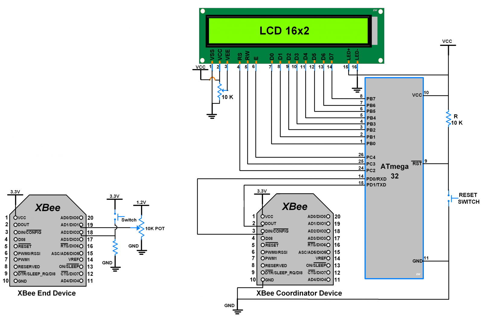
Note: In the above example, we need to configure XBee End Device pins (AD1/DIO1 & AD2/DIO2) as Analog and Digital input. Refer configuring the XBee pins section in XBee Module.
Need to know
Here we are using XBee in API mode so for basic communication purpose we are building some basic frames like
- AT COMMAND FRAME: -
- Using this frame, we can send AT command to the XBee device.
- REMOTE AT COMMAND FRAME: -
- Using this frame, we can send AT command to the XBee device located at a remote location with their address specified in the frame.
- TRANSMIT REQUEST FRAME: -
- Using this frame, we can transmit data string to the XBee device with their address specified in the frame.
- IO DATA SAMPLE FRAME: -
- Using this frame, we receive analog/digital data transmitted by the XBee device located at a remote location with their address specified in the frame.
In the below program, we are using functions that build the above-mentioned frames structure. API frame structure functions are lengthy, but easy to understand once we know each API Frame structure.
To be familiar with API frames and their structure refer to API Frame Generator in the X-CTU section in XBee Module.
XBee Communication Code for ATmega16/32
/*
 * ATmega32 XBee
 * http://www.electronicwings.com
 */

#define F_CPU 8000000UL			/* Define CPU clock Frequency 8MHz */
#include <avr/io.h>				/* Include AVR std. library file */
#include <string.h>				/* Include string library */
#include <stdio.h>				/* Include standard I/O library */
#include <stdlib.h>				/* Include standard library */
#include <util/delay.h>			/* Include delay header file */
#include <avr/interrupt.h>		/* Include avr interrupt header file */
#include <stdbool.h>			/* Include boolean library */
#include "USART_RS232_H_file.h"		/* Include USART header file */
#include "LCD_16x2_H_file.h"

#define SREG    _SFR_IO8(0x3F)		/* Define Status Register */

/* Define Required XBee Frame Type and Responses */
#define START_DELIMITER					0x7E
#define AT_COMMAND_FRAME				0x08
#define TRANSMIT_REQUEST_FRAME			0x10
#define REMOTE_AT_COMMAND_FRAME			0x17
#define IO_DATA_SAMPLE_FRAME			0x92
#define AT_COMMAND_RESPONSE_FRAME		0x88
#define REMOTE_AT_COMMAND_RESPONSE_FRAME	0x97
#define RECEIVE_PACKET_FRAME			0x90
#define TRANSMIT_STATUS_FRAME			0x8B
#define FRAME_ID						0x01
#define REMOTE_AT_COMMAND_OPT			0x02
#define TRANSMIT_REQUEST_OPT			0x00
#define TRANSMIT_REQUEST_BROADCAST_RADIUS	0x00

#define Read					0
#define Write					1

#define Vref					1.2


#define BUFFER_SIZE				100
#define DIGITAL_BUFFER_SIZE			16
#define ANALOG_BUFFER_SIZE			8

uint8_t		ReceiveBuffer[BUFFER_SIZE];
int8_t		DigitalData[DIGITAL_BUFFER_SIZE];
int16_t		AnalogData[ANALOG_BUFFER_SIZE];
uint16_t	BufferPointer	= 0,
		LastByteOfFrame	= 0;
uint32_t	Command_Value	= 0;

bool 	_IsContainsDigital 	= false,
	_IsContainsAnalog	= false;

bool Is_Data_Received()		/* Check weather data received or not  */
{
	for (uint8_t i = 0; i < BUFFER_SIZE; i++)
	{
		if (ReceiveBuffer[i] != 0 && i > 0)
			return true;
	}
	return false;
}

bool Is_Checksum_Correct()	/* Check weather received data is correct */
{
	uint16_t checksum = 0;
	for(uint8_t i = 3; i < LastByteOfFrame; i++)
		checksum = checksum + ReceiveBuffer[i];
	checksum = 0xFF - checksum;
	if(ReceiveBuffer[LastByteOfFrame] == (uint8_t)checksum
	   && LastByteOfFrame > 0)
		return true;
	else
		return false;
}

/* Sample function for parsing received buffer as per frame type */
void sample()
{
	uint8_t Frame_Type, Is_Analog;
	uint16_t Length, Is_Digital, Digital_Value;

	_IsContainsAnalog = false;
	_IsContainsDigital = false;

	/* 2 byte Frame length is at 1st and 2nd position of frame */
	Length = ((int)ReceiveBuffer[1]<<8) + ReceiveBuffer[2];
	/* 1 byte Frame type is at 3rd position of frame */
	Frame_Type = ReceiveBuffer[3];

	switch (Frame_Type)
	{
	  case (IO_DATA_SAMPLE_FRAME):	/* Parse received I/O data sample frame */
		if(Is_Data_Received() == false || Is_Checksum_Correct() == false) break;
		Is_Digital = ((int)ReceiveBuffer[16]<<8) + ReceiveBuffer[17];
		Is_Analog = ReceiveBuffer[18];
		Digital_Value = ((int)ReceiveBuffer[19]<<8) + ReceiveBuffer[20];

		if(Is_Analog != 0)
			_IsContainsAnalog = true;
		if(Is_Digital != 0)
			_IsContainsDigital = true;
/****** Check For wheather sample contains Analog/Digital Sample *********/

	     for (uint8_t i = 0; i < DIGITAL_BUFFER_SIZE; i++)
	      {
		if(((Is_Digital >> i) & 0x01) == 1 && ((Digital_Value>>i) & 0x01) != 0)
			DigitalData[i] = 1;
		else if(((Is_Digital >> i) & 0x01) == 1	&& ((Digital_Value>>i) & 0x01) == 0)
			DigitalData[i] = 0;
		else
			DigitalData[i] = -1;
	      }

	     for (uint8_t i = 0, j = 0; i < ANALOG_BUFFER_SIZE; i++)
	      {
		if(((Is_Analog >> i) & 0x01) == 1)
		  {
			if(Is_Digital != 0)
			AnalogData[i] = 256 * ReceiveBuffer[21+(j*2)] + ReceiveBuffer[22+(j*2)];
			else
			AnalogData[i] = 256 * ReceiveBuffer[19+(j*2)] + ReceiveBuffer[20+(j*2)];
			j++;
		  }
		else
		  {
			AnalogData[i] = -1;
		  }
	      }

	case (TRANSMIT_STATUS_FRAME):/* Parse received Transmit status frame */
		if(Is_Data_Received() == false || Is_Checksum_Correct() == false) break;
			break;	/* Check whether frame is correctly received */
	case (RECEIVE_PACKET_FRAME):/* Parse received Receive packet frame */
		if(Is_Data_Received() == false || Is_Checksum_Correct() == false) break;
			break;
	case (REMOTE_AT_COMMAND_RESPONSE_FRAME):
		if(Is_Data_Received() == false || Is_Checksum_Correct() == false) break;
			break;
	case (AT_COMMAND_RESPONSE_FRAME):
		if(Is_Data_Received() == false || Is_Checksum_Correct() == false) break;
			break;
	default:
			break;
	}
}

bool Get_Sample()		/* Get sample function */
{
	_delay_ms(200);		/* Wait for response */
	/* Check for if data available or not */
	for (uint16_t count = 0; Is_Data_Received() == false; count++)
	{
		if(count>50000)
			return false;
	}
	cli();			/* Disable global interrupt */
	sample();		/* Parse data in sample function */
	memset(ReceiveBuffer,0,BUFFER_SIZE);/* Clear Buffer */
	sei();			/* Enable global interrupt */
	return true;		/* Return success value */
}

void Remote_AT_Command(uint64_t Long_Address, uint16_t Short_Address, char* ATCommand, bool action)
{
	uint16_t Length,Checksum;
	if (action == Write)
	{
		/* Define parameter value depend frame length */
		if(Command_Value > 0x00FFFFFF) Length = 19;
		else if(Command_Value > 0x00FFFF) Length = 18;
		else if(Command_Value > 0x00FF) Length = 17;
		else Length = 16;
	}
	else
		Length = 15;

	Checksum = REMOTE_AT_COMMAND_FRAME + FRAME_ID;/* Calculate Checksum */
	for (int8_t i = 56 ; i >= 0; i = i-8)
		Checksum = Checksum + (Long_Address >> i);

	Checksum = Checksum + (Short_Address >> 8) +
		   Short_Address + REMOTE_AT_COMMAND_OPT +
		   ATCommand[0] + ATCommand[1];
	if (action == Write)
	Checksum = Checksum + (Command_Value >> 24) + (Command_Value >> 16) + (Command_Value >> 8) + Command_Value ;
	/* Subtract checksum lower byte from 0xFF to get 1 byte checksum */
	Checksum = 0xFF - Checksum;

	USART_TxChar(START_DELIMITER);	/* Send start with 1 byte Delimiter */
	USART_TxChar(Length >> 8);	/* Send 2 byte length */
	USART_TxChar(Length);
	USART_TxChar(REMOTE_AT_COMMAND_FRAME);	/* Send 1 byte frame type */
	USART_TxChar(FRAME_ID);		/* Send 1 byte frame ID */
	for (int8_t i = 56 ; i >= 0 ; i = i-8)	/* Send 64-bit dest. address */
		USART_TxChar(Long_Address >> i);
	USART_TxChar(Short_Address >> 8);/* Send 16-bit dest. address */
	USART_TxChar(Short_Address);
	USART_TxChar(REMOTE_AT_COMMAND_OPT);/* Send Option */
	USART_SendString(ATCommand);	/* Send AT command */

	if(action == Write)
	{
		if(Length == 19)	/* Send value */
		{
			USART_TxChar(Command_Value >> 24);
			USART_TxChar(Command_Value >> 16);
			USART_TxChar(Command_Value >> 8);
		}
		if(Length == 18)
		{
			USART_TxChar(Command_Value >> 16);
			USART_TxChar(Command_Value >> 8);
		}
		if(Length == 17)
			USART_TxChar(Command_Value >> 8);
		USART_TxChar(Command_Value);
	}
	USART_TxChar(Checksum);		/* Send Checksum */
}

void AT_Command(char* ATCommand, bool action)
{
	uint16_t Length,Checksum;

	if (action == Write)
	{
		if(Command_Value > 0x00FFFFFF) Length = 8;
		else if(Command_Value > 0x00FFFF) Length = 7;
		else if(Command_Value > 0x00FF) Length = 6;
		else Length = 5;
	}
	else
		Length = 4;

	Checksum = AT_COMMAND_FRAME + FRAME_ID + ATCommand[0] + ATCommand[1];
	if (action == Write)
	Checksum = Checksum + (Command_Value >> 24) + (Command_Value >> 16) + (Command_Value >> 8) + Command_Value ;
	Checksum = 0xFF - Checksum;

	USART_TxChar(START_DELIMITER);
	USART_TxChar(Length >> 8);
	USART_TxChar(Length);
	USART_TxChar(AT_COMMAND_FRAME);
	USART_TxChar(FRAME_ID);
	USART_SendString(ATCommand);

	if(action == Write)
	{
		if(Length == 8)
		{
			USART_TxChar(Command_Value >> 24);
			USART_TxChar(Command_Value >> 16);
			USART_TxChar(Command_Value >> 8);
		}
		if(Length == 7)
		{
			USART_TxChar(Command_Value >> 16);
			USART_TxChar(Command_Value >> 8);
		}
		if(Length == 6)
			USART_TxChar(Command_Value >> 8);
		USART_TxChar(Command_Value);
	}
	USART_TxChar(Checksum);
}

void Transmit_Request(uint64_t Long_Address, uint16_t Short_Address, char* str)
{
	uint16_t Length,Checksum;
	Length = 14 + strlen(str);

	Checksum = TRANSMIT_REQUEST_FRAME + FRAME_ID;
	for (int8_t i = 56; i >= 0; i = i-8)
		Checksum = Checksum + (Long_Address >> i);
	Checksum = Checksum + (Short_Address >> 8) + Short_Address;
	for (int8_t i = 0; str[i] != 0; i++)
		Checksum = Checksum + str[i];
	Checksum = 0xFF - Checksum;

	USART_TxChar(START_DELIMITER);
	USART_TxChar(Length >> 8);
	USART_TxChar(Length);
	USART_TxChar(TRANSMIT_REQUEST_FRAME);
	USART_TxChar(FRAME_ID);
	for (int8_t i = 56; i >=0; i = i-8)
		USART_TxChar((Long_Address >> i));
	USART_TxChar(Short_Address >> 8);
	USART_TxChar(Short_Address);
	USART_TxChar(TRANSMIT_REQUEST_BROADCAST_RADIUS);
	USART_TxChar(TRANSMIT_REQUEST_OPT);
	USART_SendString(str);
	USART_TxChar(Checksum);
}

void Write_AT_Command(char* ATCommand, uint32_t _CommandValue)
{
	Command_Value = _CommandValue;
	AT_Command(ATCommand, Write);
}

void Read_AT_Command(char* ATCommand)
{
	AT_Command(ATCommand, Read);
}

void Write_Remote_AT_Command(uint64_t Long_Address, uint16_t Short_Address, char* ATCommand, uint32_t _CommandValue)
{
	Command_Value = _CommandValue;
	Remote_AT_Command(Long_Address, Short_Address, ATCommand, Write);
}

void Read_Remote_AT_Command(uint64_t Long_Address, uint16_t Short_Address, char* ATCommand)
{
	Remote_AT_Command(Long_Address, Short_Address, ATCommand, Read);
}

ISR (USART_RXC_vect)	/* Receive ISR routine */
{
	uint8_t oldsreg = SREG;
	cli();
	/* If received byte is start delimiter then,
 	copy LastByteOfFrame & reset BufferPointer */
	if (UDR == START_DELIMITER)
	{
		ReceiveBuffer[BufferPointer] = UDR;
		LastByteOfFrame = BufferPointer;
		BufferPointer = 0;
	}
	/* Else copy data to buffer & increment BufferPointer */
	else
	{
		ReceiveBuffer[BufferPointer] = UDR;
		BufferPointer++;
	}
	SREG = oldsreg;
}

void SetTo_Broadcast()
{
	_delay_ms(500);
	Write_AT_Command("DH", 0x00000000);
	_delay_ms(500);
	Write_AT_Command("DL", 0x0000FFFF);
	_delay_ms(500);
	Read_AT_Command("WR");
	_delay_ms(1000);
}

int main(void)
{
	char _buffer[25], Volt[10];
	uint64_t Remote_Address = 0x0013A20041241CB2;
	float voltage;


	USART_Init(9600);	/* Initiate USART with 9600 baud rate */
	LCD_Init();		/* Initialize LCD */
	LCD_String_xy(1, 0, "X-Bee Network ");	/* Print initial test message */
	LCD_String_xy(2, 0, "Demo..!!");
	_delay_ms(15000);	/* XBee initialize time */
	LCD_Clear();
	sei();			/* Enable global interrupt */

	LCD_String_xy(1, 0, "Setting X-Bee to");
	LCD_String_xy(2, 0, "Broadcast mode  ");
	SetTo_Broadcast();	/* Set XBee coordinator to broadcast mode */
	LCD_Clear();

	LCD_String_xy(1, 0, "Request Samples ");
	/* Request Samples from remote X-Bee device at 100ms Sample rate */
	Write_Remote_AT_Command(Remote_Address, 0xFFFE, "IR", 100);
	_delay_ms(1500);
	LCD_Clear();

	while (1)
	{
		Get_Sample();
		if (_IsContainsDigital)
		{
			if(DigitalData[2] >= 0)
			{
			  sprintf(_buffer, "Switch = %d   ", DigitalData[2]);
			  LCD_String_xy(1, 0, _buffer);	/* print on 1st row */
			  memset(_buffer, 0, 25);	/* Clear Buffer */
			}
		}
		if (_IsContainsAnalog)
		{
			voltage = (float)AnalogData[1] * Vref / 1024.0;
			dtostrf(voltage, 3, 3, Volt);
			if(AnalogData[1] >= 0)
			{
			  sprintf(_buffer, "Pot Vtg = %sV  ", Volt);
			  LCD_String_xy(2, 0, _buffer);	/* print on 2nd row */
			  memset(_buffer, 0, 25);	/* Clear Buffer */
			  memset(Volt, 0, 10);
			}
		}
	}
}
Video of XBee Communication using ATmega16/32
Components Used |
||
|---|---|---|
| ATmega 16 ATmega 16 |
X 1 | |
| Atmega32 Atmega32 |
X 1 | |
| XBee S2 Module XBee is a radio module developed by Digi International. It is popular wireless transceiver used to send or receive data. It is used for low data rate, low power over short distance wireless communication applications such as Home Automation, Wireless sensor n/w, Industrial control, Medical data collection, Building automation etc. |
X 2 | |
| LCD16x2 Display LCD16x2 Display |
X 1 | |