Overview of Stepper Motor
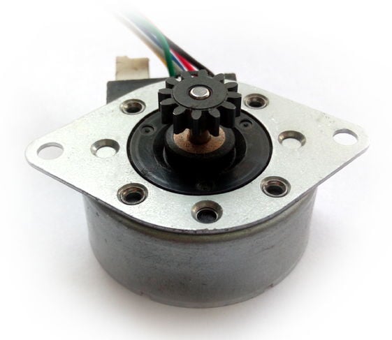
Stepper motor is a brushless DC motor that divides the full rotation angle of 360° into a number of equal steps.
- The motor is rotated by applying a certain sequence of control signals. The speed of rotation can be changed by changing the rate at which the control signals are applied.
- Various stepper motors with different step angles and torque ratings are available in the market.
- A microcontroller can be used to apply different control signals to the motor to make it rotate according to the need of the application.
For more information about Stepper Motor and how to use it, refer to the topic Stepper Motor in the sensors and modules section.
Connection Diagram of Stepper Motor with ATmega16/32
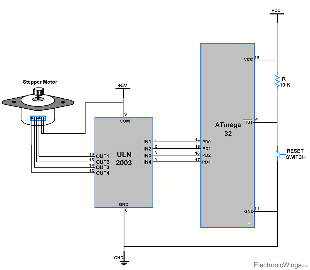
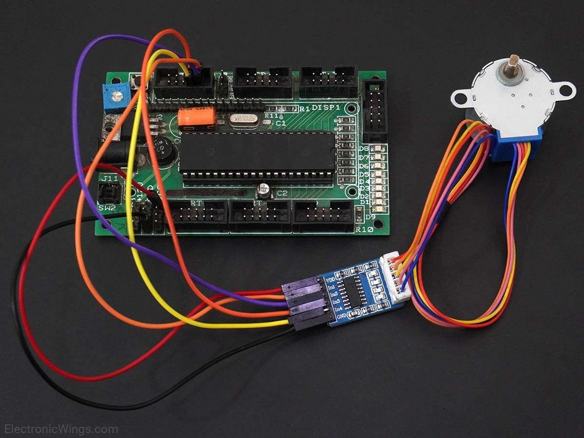
- Here we are going to interface 6 wires Unipolar Stepper Motor with ATmega32 controller.
- Only four wires are required to control the stepper motor.
- Two common wires of stepper motor connected to 5V supply.
- ULN2003 driver is used to the driving stepper motor.
- Note that to know winding coil and their center tap leads measure resistance in between leads. From center leads, we will get half the resistance value of that winding.
Control Stepper Motor Using Atmega16/32
Let’s program AVR ATmega32 to rotate the stepper motor 360° clockwise by half step sequence and 360° anticlockwise by full step sequence.
Stepper Motor Code for Atmega16/32
/*
 * ATmega32 Stepper Motor Control
 * http://www.electronicwings.com
 */


#define F_CPU 8000000UL		/* Define CPU Frequency 8MHz */
#include <avr/io.h>			/* Include AVR std. library file */
#include <util/delay.h>		/* Include delay header file */


int main(void)
{
	int period;
	DDRD = 0x0F;		/* Make PORTD lower pins as output */
	period = 100;		/* Set period in between two steps */
	while (1)
	{
		/* Rotate Stepper Motor clockwise with Half step sequence */
		for(int i=0;i<12;i++)
		{
			PORTD = 0x09;
			_delay_ms(period);
			PORTD = 0x08;
			_delay_ms(period);
			PORTD = 0x0C;
			_delay_ms(period);
			PORTD = 0x04;
			_delay_ms(period);
			PORTD = 0x06;
			_delay_ms(period);
			PORTD = 0x02;
			_delay_ms(period);
			PORTD = 0x03;
			_delay_ms(period);
			PORTD = 0x01;
			_delay_ms(period);
		}
		PORTD = 0x09;		/* Last step to initial position */
		_delay_ms(period);
		_delay_ms(1000);

		/* Rotate Stepper Motor Anticlockwise with Full step sequence */
		for(int i=0;i<12;i++)
		{
			PORTD = 0x09;
			_delay_ms(period);
			PORTD = 0x03;
			_delay_ms(period);
			PORTD = 0x06;
			_delay_ms(period);
			PORTD = 0x0C;
			_delay_ms(period);
		}
		PORTD = 0x09;
		_delay_ms(period);
		_delay_ms(1000);
	}
}
Video of Stepper Motor Control using ATmega16/32
Components Used |
||
|---|---|---|
| ATmega 16 ATmega 16 |
X 1 | |
| Atmega32 Atmega32 |
X 1 | |
| ULN2003 Motor Driver ULN2003A is a high-voltage, high-current Darlington transistor array. |
X 1 | |