Overview of Analog Joystick
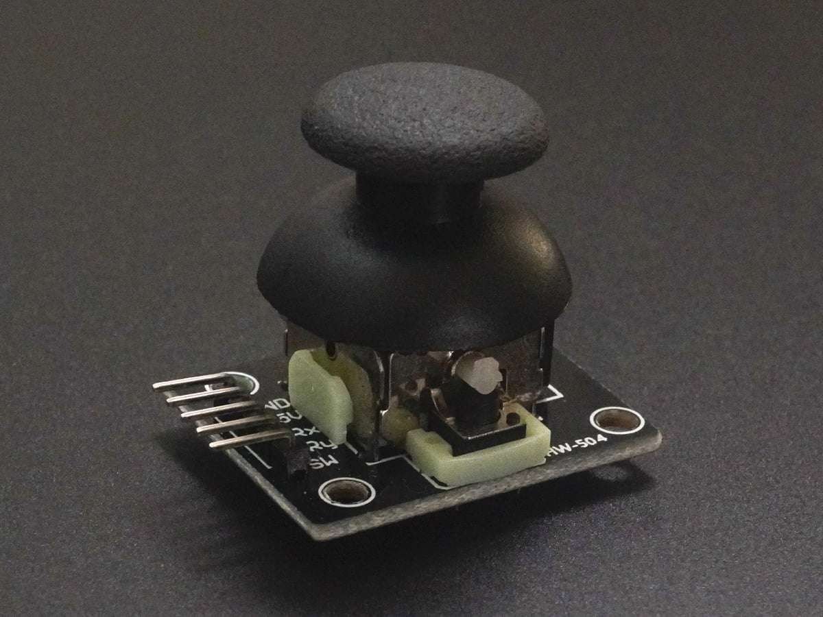
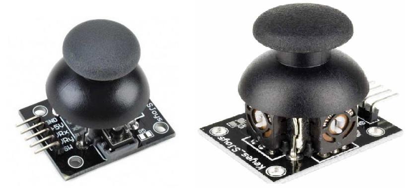
Analog Joystick is used as an input device for changing the position of the cursor in correspondence to the movement of the joystick.
It gives analog voltages in X and Y directions corresponding to the position of the joystick.
These voltages can be processed to find the position of the cursor or for moving the cursor according to the position of the joystick.
For more information about Analog Joystick and how to use it, refer to the topic Analog Joystick in the sensors and modules section.
In order to process the analog signals, we need to use ADC on the microcontroller.
For information about ADC in ATmega16 and how to use it, refer to the topic ADC in AVR ATmega16/ATmega32 in the ATmega inside section.
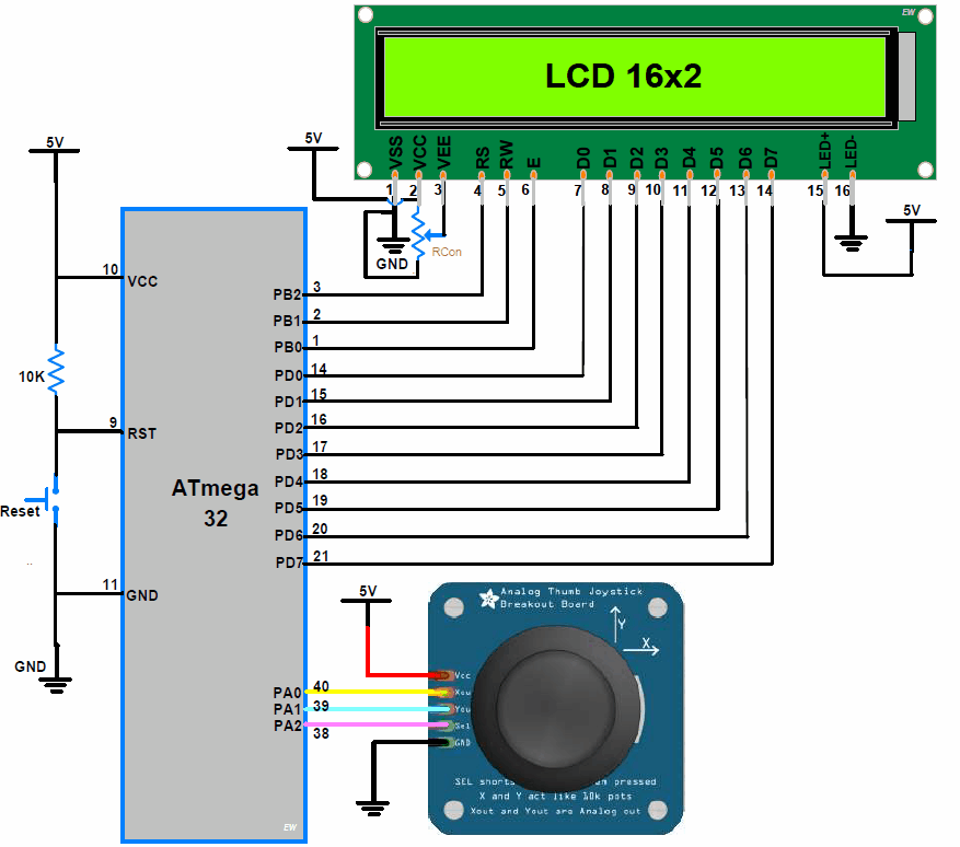
Connection Diagram of Analog Joystick with ATmega16/32
Programming of Joystick
- Let’s make the code to display the Direction of an angular movement.
- Here we also show the voltage at X and Y-axis pins at a particular movement.
- The state of Switch, whether it is pressed or not is also shown.
The code for the particular system is mainly divided into three parts:
- X-Axis and Y-Axis Position voltages:
- To measure the voltage at the terminal X-Out and Y-Out, we can use inbuilt 10-bit ADC of Controller.
- To get the voltage at the X-OUT pin, we are connecting the X-OUT pin to the 1st pin of PORTA (PA0). PA0 pin is channel 0 for ADC.
- To get the voltage at the Y-OUT pin, we are connecting the Y-OUT pin to the 2nd pin of PORTA (PA1). PA1 pin is channel 1 for ADC.
- ADC gives output in 10-bit format. It is important to Scale the ADC output in an appropriate format.
- To display the value in form of output voltage, it is required to scale the ADC output in 0 to 5. The formula used for scaling is,
Output Voltage = ((ADC value * 5)/1024);- If the output voltage is 2.5, The LCD shows C, which indicates the holder is at the center position.
- When we move the holder to an upward direction, the Y-Axis voltage starts to increase. And LCD shows U, which indicates an upward moment. At the same time, the LCD shows the value of the voltage on both pins X-axis and Y-axis.
- Similarly, according to movements, LCD shows the Downward, Left, and Right position of Holder.
2. Switch State:
This pin is connected to the ground when switch is pressed. To detection of switch pressed, it is required to set the controller pin as Input configuration and active internal pull-up resistance.
Analog Joystick Code for ATmefa16/32
/*
 Joystick interface with AVR ATmega16/ATmega32
 www.electronicwings.com
 */

#define F_CPU 8000000UL
#include <avr/io.h>
#include <util/delay.h>
#include <stdio.h>
#include "LCD_16x2_H_file.h"
#include "ADC_H.h"

int main(void)
{
	char buffer[20];
	int ADC_Value;

	ADC_Init();		/* Initialize ADC */
	LCD_Init();		/* Initialize LCD */

	while(1)
	{
		ADC_Value = ADC_Read(0);/* Read the status on X-OUT pin using channel 0 */
		sprintf(buffer, "X=%d   ", ADC_Value);
		LCD_String_xy(1, 0, buffer);

		ADC_Value = ADC_Read(1);/* Read the status on Y-OUT pin using channel 0 */
		sprintf(buffer, "Y=%d   ", ADC_Value);
		LCD_String_xy(1, 8, buffer);

		ADC_Value = ADC_Read(2);/* Read the status on SWITCH pin using channel 0 */
		if(ADC_Value < 600)
			LCD_String_xy(2, 0, "Switch pressed   ");
		else
			LCD_String_xy(2, 0, "Switch open      ");
	}
}
Video of Analog Joystick with ATmefa16/32
Components Used |
||
|---|---|---|
| Analog Joystick Joystick is an input device used to control the pointer movement in 2-dimension axis. It is mostly used in Video games. |
X 1 | |
| ATmega 16 ATmega 16 |
X 1 | |
| Atmega32 Atmega32 |
X 1 | |
| LCD16x2 Display LCD16x2 Display |
X 1 | |
Downloads |
||
|---|---|---|
|
|
ATmega16 Joystick Interface Project file | Download |