Overview of RTC
Real-Time Clock (RTC) is used for tracking time and maintaining a calendar.
Many applications require to keep records of time/date when certain events occur. RTCs are useful in such applications.
RTCs come in handy in data logging applications. They are also used in devices like computers, laptops, and mobile phones.
RTCs are powered by external batteries so that they can maintain time and date even in case of power failures.
RTCs have several registers that keep a track of time and date.
In order to use an RTC, we need to first program it with the current date and time. Once this is done, the RTC registers can be read at any time to know the time and date.
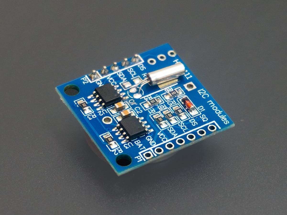
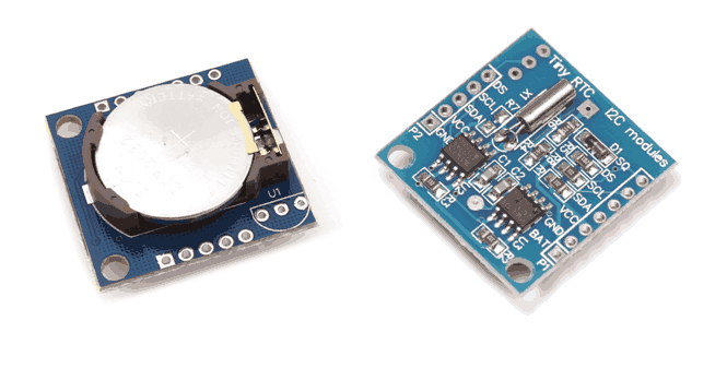
DS1307 is an RTC that works on I2C protocol.
For information on DS1307 and how to use it, refer to the topic Real-Time Clock RTC DS1307 Module in the sensors and modules section.
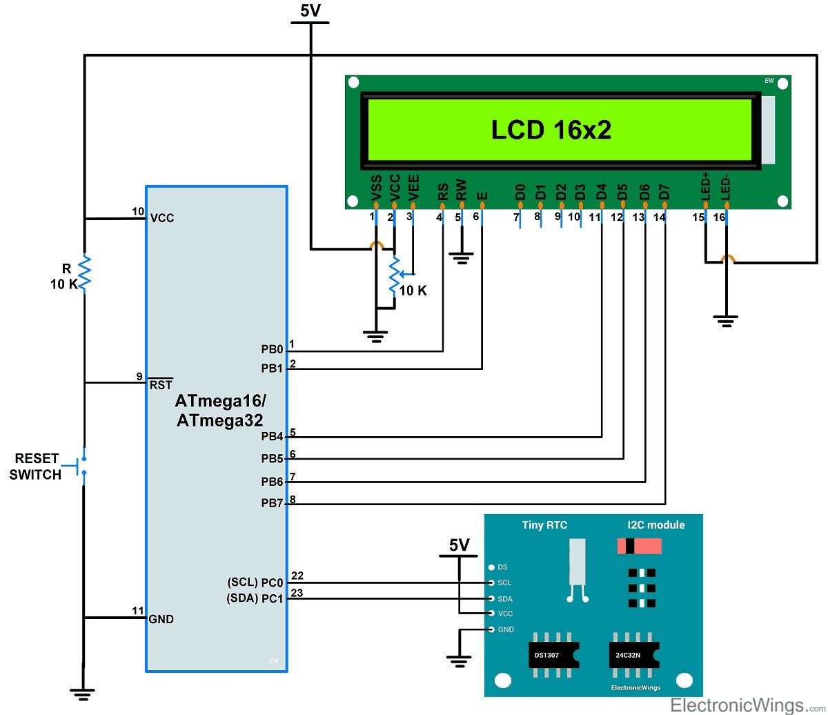
Connection Diagram of DS1307 RTC with ATmega16/32
- The following circuit diagram shows the interfacing of DS1307 RTC with AVR-based ATmega16/ATmega32 using I2C protocol.
- ATmega16/ATmega32 IC pin no.22 (PORTC.0) is SCL is connected to SCL pin of RTC and pin no. 23 (PORTC.1) is SDA is connected to the SDA of RTC shown in fig. below.
The display is connected to PORT B, and connected in the 4-bit mode shown in the figure below.
Programming for RTC DS1307 using ATmega16/32
Initially, while using RTC first time, we have to set the clock and calendar values, then RTC always keeps updating this clock and calendar values.
We will set the RTC clock and calendar values in 1st step and in the 2nd step, we will read these values.
Step1: Setting Clock and Calendar to RTC DS1307
- In RTC coding, we require the first RTC device address (slave address) through which the microcontroller wants to communicate with the DS1307.
- DS1307 RTC device address is 0xD0 (given in datasheet).
- Initialize I2C in ATmega16 /32.
- Start I2C communication with device writes address i.e. 0xD0.
- If the address is matched we get an acknowledgment signal.
- Send the Register address of seconds which is 0x00, then send the value of seconds to write in RTC. RTC address gets auto-incremented so next, we only have to send the values of minutes, hours, day, date, month, and year.
- And then stop the I2C communication.
/* function for clock */
void RTC_Clock_Write(char _hour, char _minute, char _second, char AMPM)
{
	_hour |= AMPM;
	I2C_Start(Device_Write_address);/* Start I2C communication with RTC */
	I2C_Write(0);			/* Write 0 address for second */
	I2C_Write(_second);		/* Write second on 00 location */
	I2C_Write(_minute);		/* Write minute on 01(auto increment) location */
	I2C_Write(_hour);		/* Write hour on 02 location */
	I2C_Stop();			/* Stop I2C communication */
}

/* function for calendar */
void RTC_Calendar_Write(char _day, char _date, char _month, char _year)
{
	I2C_Start(Device_Write_address);/* Start I2C communication with RTC */
	I2C_Write(3);			/* Write 3 address for day */
	I2C_Write(_day);		/* Write day on 03 location */
	I2C_Write(_date);		/* Write date on 04 location */
	I2C_Write(_month);		/* Write month on 05 location */
	I2C_Write(_year);		/* Write year on 06 location */
	I2C_Stop();			/* Stop I2C communication */
}
Step2: Reading Time and Date value from RTC DS1307
- In the second step, we learn how to read the data from the RTC, i.e. second, minute, hours, etc.
- Start the I2C communication with device writes address i.e. 0xD0.
- Then write the register value from where we have to read the data (we read from location 00 i.e. read the second).
- Then repeated start I2C with device read address i.e. 0xD1.
- Now Read the data with acknowledgment from location 00.
- For reading the last location always read with the negative acknowledgment, then the device will understand this is the last data read from the device.
- For reading the next location of the register address will get auto-incremented.
DS1307 RTC Code for ATmega16/32
/*
 * ATmega 16/32 interfacing with RTC DS1307
 * http://www.electronicwings.com
 */

#include <avr/io.h>
#include <stdio.h>
#include <string.h>
#include <stdbool.h>
#include "I2C_Master_H_file.h"
#include "LCD16x2_4Bit.h"

#define Device_Write_address	0xD0	/* Define RTC DS1307 slave write address */
#define Device_Read_address	0xD1	/* Make LSB bit high of slave address for read */
#define TimeFormat12		0x40	/* Define 12 hour format */
#define AMPM			0x20


int second,minute,hour,day,date,month,year;

bool IsItPM(char hour_)
{
	if(hour_ & (AMPM))
	return 1;
	else
	return 0;
}

void RTC_Read_Clock(char read_clock_address)
{
	I2C_Start(Device_Write_address);/* Start I2C communication with RTC */
	I2C_Write(read_clock_address);	/* Write address to read */
	I2C_Repeated_Start(Device_Read_address);/* Repeated start with device read address */

	second = I2C_Read_Ack();	/* Read second */
	minute = I2C_Read_Ack();	/* Read minute */
	hour = I2C_Read_Nack();		/* Read hour with Nack */
	I2C_Stop();			/* Stop i2C communication */
}

void RTC_Read_Calendar(char read_calendar_address)
{
	I2C_Start(Device_Write_address);
	I2C_Write(read_calendar_address);
	I2C_Repeated_Start(Device_Read_address);

	day = I2C_Read_Ack();		/* Read day */
	date = I2C_Read_Ack();		/* Read date */
	month = I2C_Read_Ack();		/* Read month */
	year = I2C_Read_Nack();		/* Read the year with Nack */
	I2C_Stop();			/* Stop i2C communication */
}

int main(void)
{
	char buffer[20];
	char* days[7]= {"Sun","Mon","Tue","Wed","Thu","Fri","Sat"};

	I2C_Init();			/* Initialize I2C */
	lcdinit();			/* Initialize LCD16x2 */

    while(1)
    {
		RTC_Read_Clock(0);	/* Read clock with second add. i.e location is 0 */
		if (hour & TimeFormat12)
		{
			sprintf(buffer, "%02x:%02x:%02x  ", (hour & 0b00011111), minute, second);
			if(IsItPM(hour))
			strcat(buffer, "PM");
			else
			strcat(buffer, "AM");
			lcd_print_xy(0,0,buffer);
		}

		else
		{
			sprintf(buffer, "%02x:%02x:%02x  ", (hour & 0b00011111), minute, second);
			lcd_print_xy(0,0,buffer);
		}
		RTC_Read_Calendar(3);	/* Read calendar with day address i.e location is 3 */
		sprintf(buffer, "%02x/%02x/%02x %3s ", date, month, year,days[day-1]);
		lcd_print_xy(1,0,buffer);
    }
}
Video of RTC using ATmega16/32
Components Used |
||
|---|---|---|
| DS1307 RTC DS1307 RTC DS1307 RTC DS1307 RTC |
X 1 | |
| ATmega 16 ATmega 16 |
X 1 | |
| Atmega32 Atmega32 |
X 1 | |
| LCD16x2 Display LCD16x2 Display |
X 1 | |