Overview of Ultrasonic Sensor
- Ultrasonic Module HC-SR04 works on the principle of SONAR and RADAR system.
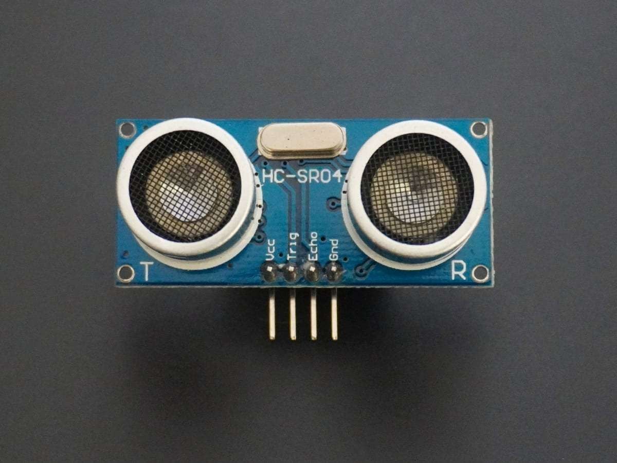
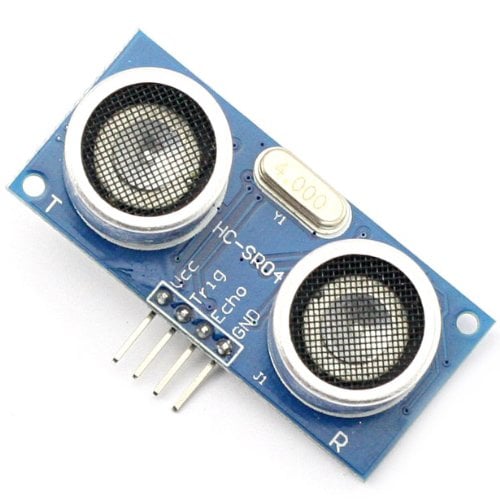
- HC-SR-04 module has an ultrasonic transmitter, receiver, and control circuit on a single board.
- The module has only 4 pins, Vcc, Gnd, Trig, and Echo.
- When a pulse of 10µsec or more is given to the Trig pin, 8 pulses of 40 kHz are generated. After this, the Echo pin is made high by the control circuit in the module.
- The echo pin remains high till it gets an echo signal of the transmitted pulses back.
- The time for which the echo pin remains high, i.e. the width of the Echo pin gives the time taken for generated ultrasonic sound to travel towards the object and return.
- Using this time and the speed of sound in air, we can find the distance of the object using a simple formula for distance using speed and time.
For more information about ultrasonic module HC-SR04 and how to use it, refer to the topic Ultrasonic Module HC-SR04 in the sensors and modules section.
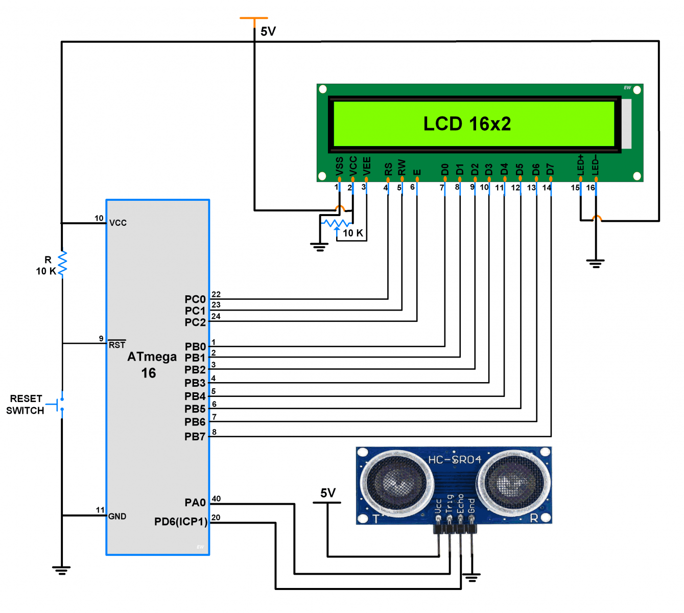
Connection Diagram of Ultrasonic Sensor HC-SR04 with ATmega16/32
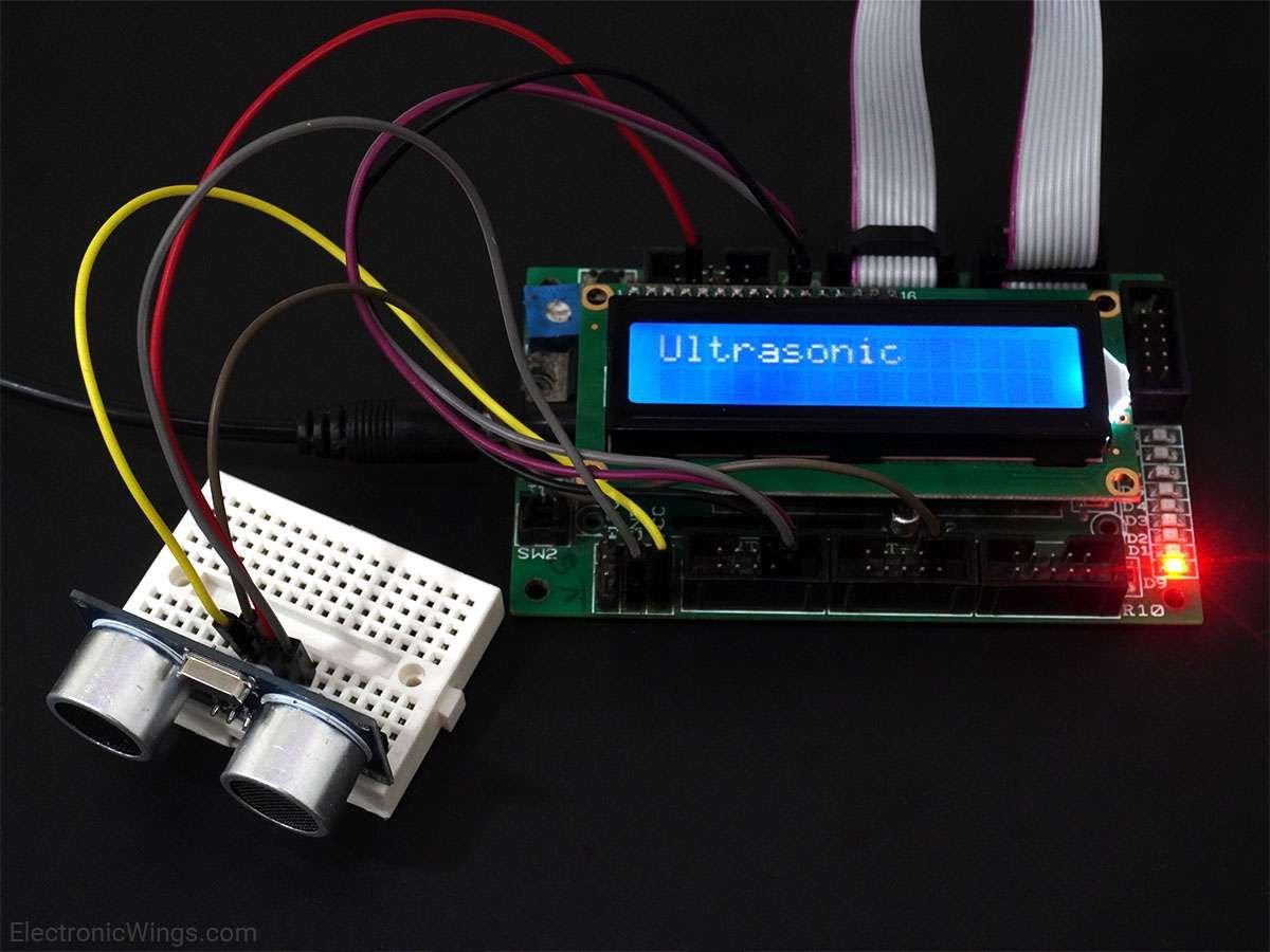
Measure Distance and Print on LCD16x2 using Ultrasonic Sensor and Atmega16 Microcontroller
Let’s design an application in which we will find the distance to an object by interfacing ultrasonic module HC-SR04 with AVR ATmega16 and display the distance on 16x2 LCD.
Steps of Programming
- ATmega16 microcontroller needs to transmit at least 10 us trigger pulse to the HC-SR04 Trig Pin.
- After getting a trigger pulse, HC-SR04 automatically sends eight 40 kHz sound waves and the microcontroller waits for rising edge output at the Echo pin.
- When the rising edge capture occurs at the Echo pin which is connected to an input of ATmega16, start Timer of ATmega16 and again wait for a falling edge on the Echo pin.
- As soon as the falling edge is captured at the Echo pin, the microcontroller reads the count of the Timer. This time count is used to calculate the distance to an object.
Here we are using the input capture mode of ATmega16 on PD6(ICP1) pin as shown in the above interfacing diagram.
Calculation (distance in cm) (H1)
Sound velocity = 343.00 m/s = 34300 cm/s
The distance of Object (in cm) =
=
=
Now, here we have selected an internal 8 MHz oscillator frequency for ATmega16, with No-presale for timer frequency. Then time to execute 1 instruction is 0.125 us.
So, the timer gets incremented after 0.125 us time elapse.
= 17150 x (TIMER value) x 0.125 x 10^-6 cm
= 0.125 x (TIMER value)/58.30 cm
= (TIMER value) / 466.47 cm
Ultrasonic Sensor HC-SR04 Code for ATmega16/32
/*
 * Ultrasonic sensor HC-05 interfacing with AVR ATmega16
 * http://www.electronicwings.com
 */

#define F_CPU 8000000UL
#include <avr/io.h>
#include <avr/interrupt.h>
#include <util/delay.h>
#include <string.h>
#include <stdlib.h>
#include "LCD_16x2_H_file.h"	/* Include LCD header file */

#define  Trigger_pin	PA0	/* Trigger pin */

int TimerOverflow = 0;

ISR(TIMER1_OVF_vect)
{
	TimerOverflow++;	/* Increment Timer Overflow count */
}

int main(void)
{
	char string[10];
	long count;
	double distance;

	DDRA = 0x01;		/* Make trigger pin as output */
	PORTD = 0xFF;		/* Turn on Pull-up */

	LCD_Init();
	LCD_String_xy(1, 0, "Ultrasonic");

	sei();			/* Enable global interrupt */
	TIMSK = (1 << TOIE1);	/* Enable Timer1 overflow interrupts */
	TCCR1A = 0;		/* Set all bit to zero Normal operation */

	while(1)
	{
		/* Give 10us trigger pulse on trig. pin to HC-SR04 */
		PORTA |= (1 << Trigger_pin);
		_delay_us(10);
		PORTA &= (~(1 << Trigger_pin));

		TCNT1 = 0;	/* Clear Timer counter */
		TCCR1B = 0x41;	/* Capture on rising edge, No prescaler*/
		TIFR = 1<<ICF1;	/* Clear ICP flag (Input Capture flag) */
		TIFR = 1<<TOV1;	/* Clear Timer Overflow flag */

		/*Calculate width of Echo by Input Capture (ICP) */

		while ((TIFR & (1 << ICF1)) == 0);/* Wait for rising edge */
		TCNT1 = 0;	/* Clear Timer counter */
		TCCR1B = 0x01;	/* Capture on falling edge, No prescaler */
		TIFR = 1<<ICF1;	/* Clear ICP flag (Input Capture flag) */
		TIFR = 1<<TOV1;	/* Clear Timer Overflow flag */
		TimerOverflow = 0;/* Clear Timer overflow count */

		while ((TIFR & (1 << ICF1)) == 0);/* Wait for falling edge */
		count = ICR1 + (65535 * TimerOverflow);	/* Take count */
		/* 8MHz Timer freq, sound speed =343 m/s */
		distance = (double)count / 466.47;

		dtostrf(distance, 2, 2, string);/* distance to string */
		strcat(string, " cm   ");	/* Concat unit i.e.cm */
		LCD_String_xy(2, 0, "Dist = ");
		LCD_String_xy(2, 7, string);	/* Print distance */
		_delay_ms(200);
	}
}
Video of Distance Measurement using Ultrasonic Sensor and Atmega16 Microcontroller
Components Used |
||
|---|---|---|
| ATmega 16 ATmega 16 |
X 1 | |
| Atmega32 Atmega32 |
X 1 | |
| Ultrasonic Module HC-SR04 Ultrasonic module HC-SR04 is generally used for finding distance value and obstacle detection. It can operate in the range 2cm-400cm. |
X 1 | |
| LCD16x2 Display LCD16x2 Display |
X 1 | |
Downloads |
||
|---|---|---|
|
|
ATmega HC-SR04 Ultrasonic Project file | Download |