Overview of OLED Module
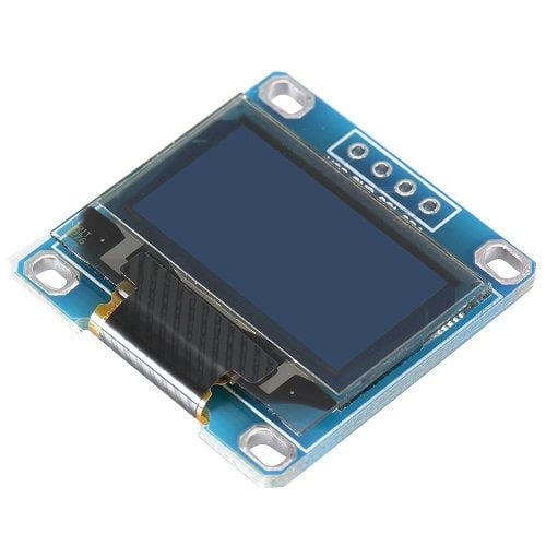
The OLED module shown in the above image is a very popular module available in the market.
There are many variants of this module available in the market, having different resolutions, communication protocol, or pixel colors.
These OLED modules are driven by SSD1306 IC which is a driver IC for 128x64 Dot Matrix OLED segments. The SSD1306 has its own controller and supports both SPI and I2C communication protocols. Hence, there are various OLED modules in the market, some that support only SPI communication, some that support only I2C communication, and some that support both I2C and SPI communication. (Different number of pins for different modules)
Since the driver IC supports 128x64 resolution, there are some variants that have a lesser resolution like 128x32.
Different modules support different colors like blue, yellow, white. Some modules support multiple colors as well. You will need to check the specifications of your display module to know which colors are supported.
We are using 4-pin I2C supported 128x64 OLED module similar to the one shown in the above image.
For more information about OLED and how to use it, refer to the topic SSD1306 OLED Display in the sensors and modules section.
128x64 OLED Display Pinout
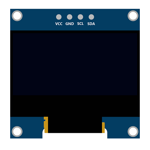
The above image shows a 128x64 I2C based OLED module.
VCC: This is the power pin for the module. A supply of 3.3V or 5V can be provided to this pin to power the display.
GND: This is the ground pin for the module.
SCL and SDA: These are the serial clock and serial data pins for I2C communication.
Connection Diagram of 128x64 OLED Display with MSP-EXP430G2 TI Launchpad
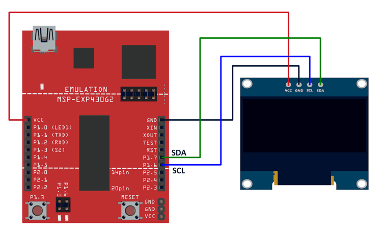
Important: The SCL and SDA for MSP-EXP430G2 TI Launchpad are on pins 14 (P1_6) and 15 (P1_7) respectively. The Energia IDE makes use of software-based I2C implementation (twi_sw) for MSP-EXP430G2 TI Launchpad. This software-based I2C implementation is defined with pins 9 (P2_1) and 10 (P2_2) as SCL and SDA pins. Hence, we need to use these pins for the I2C functions (that are used in most of the libraries) of Energia to work on the MSP-EXP430G2 TI Launchpad board. This has been done on Energia 17 and 18 (We have not checked the earlier version of the IDE).
This is not the case for all the Launchpad boards. This has been done so that the booster packs provided by TI work on all the launchpads.
Note: Here, we have used the hardware I2C pins of the MSP-EXP430G2 board. The hardware I2C implementation is faster than software I2C implementation. It is easy to change the I2C speed from 100 kHz to a higher speed (101-400 kHz) for the hardware I2C. For software I2C, it is not as easy to achieve the same.
The higher speed is required so that the OLED is cleared at a faster rate and the transition between images is smoother.
In order to use the hardware I2C pins, a few changes need to be made to certain files in Energia. Some changes also need to be made for using hardware I2C at higher speeds.
For changing the default I2C from software I2C to hardware I2C
- Find the file named pins_energia.h in the Energia IDE folder.
We had unzipped the Energia IDE in our D drive in a folder named TI_Launchpad_MSP430G2. The pins_energia.h file for MSP-EXP430G2553LP was found as shown in the path below.
D:\TI_Launchpad_MSP430G2\energia-1.6.10E18\hardware\energia\msp430\variants\MSP-EXP430G2553LP - Similarly, find the file in the folder of your IDE.
In the pins_energia.h file, find#define DEFAULT_I2C -1and replace it with#define DEFAULT_I2C 0
The file needs to be saved before uploading the sketch again for the changes to take effect.
(Use the find option and search DEFAULT_I2C in the file instead of searching the entire file. There is only one instance of this definition, so there should be no problems in finding it.)
The sketch given below will now work perfectly if the interfacing diagram given above is used.
If software I2C is used (above-mentioned changes are not made), you will have to use pins 9 (P2_1) and 10 (P2_2) as SCL and SDA pins respectively. The sketch will work even in this case, but the transitions between images and clearing of the display will not be as fast and smooth as compared to while using hardware I2C.
For changing the hardware I2C speed above 100kHz (max 400kHz)
By using the hardware I2C as mentioned above, you can get smooth and fast transitions between images and fast clearing of images.
This can be made even better by increasing the speed of the hardware I2C.
- Find the file named twi.h in the Energia IDE folder.
There are 2 files with this name in two different folders in the IDE. Follow the folder structure given in the path below to find the file to be edited.
We had unzipped the Energia IDE in our D drive in a folder named TI_Launchpad_MSP430G2. The twi.h file to be edited can be found as shown in the path below.
D:\TI_Launchpad_MSP430G2\energia-1.6.10E18\hardware\energia\msp430\cores\msp430 - Similarly, find the file in the folder of your IDE.
In the twi.h file, find#define TWI_FREQ 100000Land replace it with#define TWI_FREQ 400000L(400000L is the maximum value, you can even use a smaller value like 200000L)
The file needs to be saved before uploading the sketch again for the changes to take effect.
(Use the find option and search TWI_FREQ in the file instead of searching the entire file. There is only one instance of this definition, so there should be no problems in finding it.)
You can see the difference in speed after making this change once the sketch is uploaded.
Example
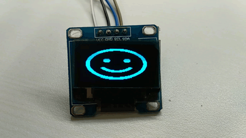
Displaying text and images on the SSD1306 OLED display.
Here, we will display simple text on the SSD1306 OLED display followed by a few images that will be displayed in a loop.
128x64 OLED Code for MSP-EXP430G2 TI Launchpad
#include <Wire.h>
#include "Font.h"
#include <string.h>
#include "images.h"

#define OLED_Write_Address 0x3C

void OLED_Data(char *DATA) /* Function for sending data to OLED */
{
  int len = strlen(DATA);
  for (int g=0; g<len; g++)
  {
    for (int index=0; index<5; index++)
    {
      Wire.beginTransmission(OLED_Write_Address); /* Begin transmission to slave device */
	  /* Queue data to be transmitted */
      Wire.write(0x40); /* For Data Transmission, C = 0 and D/C = 1 */
      Wire.write(ASCII[DATA[g] - 0x20][index]);
      Wire.endTransmission(); /* Transmit the queued bytes and end transmission to slave device */
    }
  }
}

void OLED_Command(char DATA) /* Function for sending command to OLED */
{
  Wire.beginTransmission(OLED_Write_Address); /* Begin transmission to slave device */
  /* Queue data to be transmitted */
  Wire.write(0x00); /* For Data Transmission, C = 0 and D/C = 0 */
  Wire.write(DATA);
  Wire.endTransmission(); /* Transmit the queued bytes and end transmission to slave device */
}

void OLED_clear(void) /* Function for clearing OLED */
{
  OLED_setXY(0x00, 0x7F, 0x00, 0x07); /* Column Start Address 0, Column End Address 127, Page Start Address 0, Page End Address 7  */
  for (int k=0; k<=1023; k++)
  {
    Wire.beginTransmission(OLED_Write_Address); /* Begin transmission to slave device */
	/* Queue data to be transmitted */
    Wire.write(0x40); /* For Data Transmission, C = 0 and D/C = 1 */
    Wire.write(0x00);
    Wire.endTransmission(); /* Transmit the queued bytes and end transmission to slave device */
  }
}

void OLED_setXY(char col_start, char col_end, char page_start, char page_end) /* Function for setting cursor for writing data */
{
  Wire.beginTransmission(OLED_Write_Address); /* Begin transmission to slave device */
  /* Queue data to be transmitted */
  Wire.write(0x00); /* For Data Transmission, C = 0 and D/C = 0 */
  Wire.write(0x21); /* Set Column Start and End Address */
  Wire.write(col_start); /* Column Start Address col_start */
  Wire.write(col_end); /* Column End Address col_end */
  Wire.write(0x22); /* Set Page Start and End Address */
  Wire.write(page_start); /* Page Start Address page_start */
  Wire.write(page_end); /* Page End Address page_end */
  Wire.endTransmission(); /* Transmit the queued bytes and end transmission to slave device */
}

void OLED_init(void) /* Function for initializing OLED */
{
  OLED_Command(0xAE); /* Entire Display OFF */
  OLED_Command(0xD5); /* Set Display Clock Divide Ratio and Oscillator Frequency */
  OLED_Command(0x80); /* Default Setting for Display Clock Divide Ratio and Oscillator Frequency that is recommended */
  OLED_Command(0xA8); /* Set Multiplex Ratio */
  OLED_Command(0x3F); /* 64 COM lines */
  OLED_Command(0xD3); /* Set display offset */
  OLED_Command(0x00); /* 0 offset */
  OLED_Command(0x40); /* Set first line as the start line of the display */
  OLED_Command(0x8D); /* Charge pump */
  OLED_Command(0x14); /* Enable charge dump during display on */
  OLED_Command(0x20); /* Set memory addressing mode */
  OLED_Command(0x00); /* Horizontal addressing mode */
  OLED_Command(0xA1); /* Set segment remap with column address 127 mapped to segment 0 */
  OLED_Command(0xC8); /* Set com output scan direction, scan from com63 to com 0 */
  OLED_Command(0xDA); /* Set com pins hardware configuration */
  OLED_Command(0x12); /* Alternative com pin configuration, disable com left/right remap */
  OLED_Command(0x81); /* Set contrast control */
  OLED_Command(0x80); /* Set Contrast to 128 */
  OLED_Command(0xD9); /* Set pre-charge period */
  OLED_Command(0xF1); /* Phase 1 period of 15 DCLK, Phase 2 period of 1 DCLK */
  OLED_Command(0xDB); /* Set Vcomh deselect level */
  OLED_Command(0x20); /* Vcomh deselect level ~ 0.77 Vcc */
  OLED_Command(0xA4); /* Entire display ON, resume to RAM content display */
  OLED_Command(0xA6); /* Set Display in Normal Mode, 1 = ON, 0 = OFF */
  OLED_Command(0x2E); /* Deactivate scroll */
  OLED_Command(0xAF); /* Display on in normal mode */
}

void OLED_image(const unsigned char *image_data)   /* Function for sending image data to OLED */
{
  OLED_setXY(0x00, 0x7F, 0x00, 0x07);
  for (int k=0; k<=1023; k++)
  {
    Wire.beginTransmission(OLED_Write_Address); /* Begin transmission to slave device */
	/* Queue data to be transmitted */
    Wire.write(0x40); /* For Data Transmission, C = 0 and D/C = 1 */
    Wire.write(image_data[k]);
    Wire.endTransmission(); /* Transmit the queued bytes and end transmission to slave device */
  }
}


void setup() {
  Wire.begin(); /* Initiate wire library and join I2C bus as a master */
  OLED_init(); /* Initialize OLED */
  delay(100);
  OLED_clear(); /* Clear OLED */
  delay(1000);
  OLED_image(Launchpad_Logo);
  delay(2000);
  OLED_clear();
  delay(200);
  OLED_setXY(0x31, 0x7F, 0x03, 0x02);
  OLED_Data("Smiley");
  OLED_setXY(0x36, 0x7F, 0x04, 0x03);
  OLED_Data("Demo");
  OLED_setXY(0x00, 0x7F, 0x00, 0x07);
  delay(2000);
}

void loop() {
  OLED_image(Smiley_1);
  delay(200);
  OLED_image(Smiley_2);
  delay(200);
  OLED_image(Smiley_3);
  delay(200);
  OLED_image(Smiley_4);
  delay(200);
}
Output
Components Used |
||
|---|---|---|
| TI Launchpad MSP-EXP430G2 TI Launchpad MSP-EXP430G2 |
X 1 | |
| SSD1306 OLED display OLED (Organic Graphic Display) display modules are compact and have high contrast pixels which make this display easily readable. They do not require backlight since the display creates its own light. Hence they consume less power. It is widely used in Smartphones, Digital display. |
X 1 | |
Downloads |
||
|---|---|---|
|
|
OLED_Interfacing_With_TI_Launchpad_INO | Download |